Continue to Site

Welcome to EDAboard.com

Welcome to our site! EDAboard.com is an international Electronics Discussion Forum focused on EDA software, circuits, schematics, books, theory, papers, asic, pld, 8051, DSP, Network, RF, Analog Design, PCB, Service Manuals... and a whole lot more! To participate you need to register. Registration is free. Click here to register now.

Desirable Vout Ripple

Status
Not open for further replies.

WBrumble

Junior Member level 3
Joined
Nov 13, 2015
Messages
26
Helped
0
Reputation
0
Reaction score
0
Trophy points
1
Activity points
261
All,

What is a good value for "desirable voltage ripple" on the output of a smps powering a high power LED?

Cout (min) = ΔI / 8 • Fsw • ΔV.

Cout (min) = 0.115 / 8 • 0.09 • ____

Thanks guys.

PS. The document I'm reading from Linear Technology states that a good current ripple is %30. Do you guys agree?
 

Hi,

For a LED a 30% current ripple shouldn't be problematic.

Are you sure it is not the inductor ripple current, or the capacitir ripple current.

Klaus
 
I would call it "tolerable", not "desirable". I've never
seen any use, or seen anyone ask for more Vripple.
Current ripple scaling is important to current mode
control schemes but your two "goalposts" are the
ripple that makes the current comparator work
clean (low enough jitter) and the ripple that violates
output voltage ripple, against the filter (cost, area).
But voltage ripple at the load has no upside; you
only need to meet "acceptable" at acceptable BOM
cost.
 
Thanks for the help guys!

Inductor current ripple, was just curious if 30% is a good percentage to go by.

And I read in a texas instrument document that 25mV is a good rule of thumb for max Vout ripple P-P. Do you guys agree?
 

Hi,

25mV is a good value to start when you want to build a power supply for electronics.
I don´t think this value applies for a LED supply.

***
Currently I´m involveld in a discussion about light quality.
Many LED supplies use PWM dimming. 0% / 100% ON/OFF with relatively low frequency like 200Hz or less.
This causes some stroboscopic effect. Maybe one doesn´t recognize when you are still, but when you move your eyes, or move a reflecting thing then it may cause some visual effects.
Maybe this is problemtic when you work with some high speed rotating machines.

* The higher the frequency the smaller is the effect.
* the lower the bright/dark ratio, the smaller is the effect.
* the softer the transition from bright to dark the smaller is the effect.

You talk about voltage ripple, but what counts its the current ripple in the LED, because the current is about proportional to the brightness.

To calculate the current ripple from the voltage ripple you have to multiply the voltage ripple with the differential resistance of the LED:
Ipp = Vpp x r (not R)

Klaus
 
Sounds like you mean the vout ripple on the output of the smps that supplies the led........as long as you dont over ripple current the cap then you can have a lot of ripple.......but remember that if your vout ripple gets ridiculously high, then the vout/vin equation wont conform to the standard. (eg for a buck its vout = D.vin)..then again , you may not care about that.
If you can get the led lit up and make the smps stable, and pass emc, and you dont over ripple current the cap, then who cares what the ripple is. (you arent likely to be able to see smps ripple frequency in a led if it affects the current and makes it oscillate at the swithching frequency.
 
Thanks for the reply man.

What's causing this current ripple when the PWM is turned low?

So I've calculated everything up and came up with the following.

Vin – 12vdc
Vout – 3.1vdc
Iout– 350mA
Led driver – LT3517
Led – Cree Xlamp XM-L Color (White Die)
IC frequency – 500kHz
Pwm frequecy - 500kHz

Inductor selection:

Dbuck = Vled / Vin

3.1/ 12 = .2583

Tsw = 1/Frequency

1/500,000 = .000002

ΔI = Percentage of current ripple x Iout

.30 x .350 = .105

L(µH) = Dbuck • Tsw(µs) • (Vin – Vled) / ΔI

.2583 x .000002 x 8.9 / .105 = L(µH) = 0.000043788

Inductor = 43.7uH

There isn't a calculation for the output capacitor in the document for the IC, so I sourced a document from a google search and found a Texas Instrument document on buck converter design and it says to use the following to calculate the output capacitor. Also read in that same document that 25mV is a good set point for output voltage ripple as the following equation require you to put in a value for the
desired output voltage ripple.

Capacitor selection:

Cout(min) = ΔIL / 8 x Fsw x Δvout

.105 / 8 x 500,000 x .025 = .00000105

Capacitor Out = 1.05uF

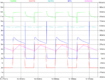
Voltage probed after mosfet and before LED = Green(n003)
Voltage probed after led before inductor = Teal(n004)
PWM voltage = Red(n012)
Current through LED = Blue(D2)
Current through inductor = Purple(Inductor)
SCOPE.png
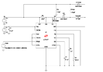
Schematic of the circuit
DRAWING.png
 
Last edited:

Status
Not open for further replies.

Similar threads

Part and Inventory Search

Welcome to EDABoard.com

Sponsor

Back
Top