Continue to Site

Welcome to EDAboard.com

Welcome to our site! EDAboard.com is an international Electronics Discussion Forum focused on EDA software, circuits, schematics, books, theory, papers, asic, pld, 8051, DSP, Network, RF, Analog Design, PCB, Service Manuals... and a whole lot more! To participate you need to register. Registration is free. Click here to register now.

[SOLVED] Power supply reality very different to prior calculations

Status
Not open for further replies.

d123

Advanced Member level 5
Joined
Jun 7, 2015
Messages
2,505
Helped
494
Reputation
992
Reaction score
525
Trophy points
1,393
Location
Spain
Activity points
27,148
Hi,

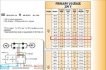
I made a basic linear AC/DC power supply, and wanted to ask why my calculations, based on the Hammond Rectifier Relationships pdf were way off reality, not sure what I'm still getting wrong.

It's a dual secondary. 2VA. 2 x 12V AC secondaries. 83mA AC per secondary.

Transformer datasheet says VSec no load = 20V AC.

As I don't have 10mA slow-blow fuses I had to use a fast-blow 100mA on the primary side, beggars can't be choosers, eh!

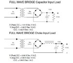
I calculated 16V DC (12V AC x 1.41), but measured 23V - 24V after the filter capacitors with "no load" (as the 7805 + an LED don't seem to count?), down to 18.7V with the right load. Had to add the dropping resistor(s) to take the strain off the 7805 as I'd calculated about 12V in, not 23 or 18...

Calculated I DC = 0.62 x I Sec AC = 50mA per secondary if I sec AC is 83mA.

The maximum the circuit can produce is 42mA DC, and that after connecting the secondaries in parallel to maximise the transformer power (not double the voltage, but wanting to double the current) and at least get about 60mA out of the thing, but it's not happening, evidently at 42mA - Why is that possible, please? What may I have done wrong, or is it just that this type of supply has such low efficiency that that is about as good as can be expected?

I gather that from (admittedly only a couple of) articles and the Hammond power supply that uses an inductor/choke, that to maximise power that one is the only circuit to do so, capacitor filter alone places current and voltage out of phase, hence poor efficiency, and even so it seems the efficiency is still very poor with the choke - from what I read that soon this type of power supply won't pass (can't remember specifically) EU or international PFC standards...

Sorry for a "not this kind of question, again...," but would appreciate any wisdom regarding why the power supply turned out so feeble, thank you.
 

Attachments

  • seedling power supply.JPG
    seedling power supply.JPG
    45.5 KB · Views: 158
  • Rectifier relationships excerpt.JPG
    Rectifier relationships excerpt.JPG
    40.9 KB · Views: 152

1. I assume Vsec=20V; current at short circuit will be 50mA for 1W; this is for each secondary.

2. You did not mention the input voltage; so please check the Vsec (no load) with a multimeter and confirm the 20V output.

3. No load DC after filtering will be 20*1.41= 28V and you subtract two diode drops. You will get around 26V.

4. What is the right load?

5. Inductor will have no effect at zero current but will contribute some small R. (ignore that)

6. Connecting the two secondaries in parallel will increase the current capacity to 100mA (max)

7. DC current will be around 60-70% of this value. That depends on the capacitor value and the winding R

8. Input side 220||470 resistor is redundant; they waste power and reduce current. It will demand a bigger capacitor.

9. Capacitor filter does not consume energy and hence does not contribute to loss of efficiency. But it all depends on how you define efficiency.
 
  • Like
Reactions: d123

    d123

    Points: 2
    Helpful Answer Positive Rating
What is the full part number of the 7805 you are using. If you can only get 42 mA out it sounds like you are going into thermal shut down.

Worst case 7805 power dissipation.

full load = 100 mA

At full load per transformer spec your secondary's should be 12 vac.

12 vac x 1.414 = 16.968 DC - 2 diode drops (1.4 vdc) = 15.568 vdc

15.568 vdc - 5vdc out = 10.568 vdc dropped across the 7805.

P = I x E, .1 A x 10.568 vdc = 1.0568 Watts
 
  • Like
Reactions: d123

    d123

    Points: 2
    Helpful Answer Positive Rating
Hi c_mitra,

1. I've attached the specs from the transformer datasheet.

2. Sorry, had already added 7805 and "it's on/not completely faulty" LED before measuring with DMM.
- Without the actual 55mA load ( a small CC circuit), readings were: 23V on filter caps output, with the load DMM read 18.7V before the 7805/after filter caps.
- Added 200R dropping resistor to get rid of ~10V in front of 7805 (440mW wasted). Was too much and 7805 didn't have enough dropout voltage, so paralleled the 470R to get ||~140R and drop about 7.7V (424mW wasted).

Original calculations for 7805 were:

12V, 50mA in = (0.05A x 7V) + (0.008A x 12V) = 446mW
0.446 x 50ºC = 22.3ºC
23ºC + 80ºC = 103ºC operating junction temp.


3. Puffffffffffffff..... What does 12V AC on the transformer and in the datasheet refer to then if the unloaded voltage is 20V AC?

4. Should be 54mA for the load (circuit being powered, 5 - 8 of which should be 7805 ground pin current) + ~6mA for the "it looks safe to use" LED.

5. Is the choke rectifier circuit for a fixed, known current load, then?

6. It apparently hasn't, unless FlapJack is correct that the LM7805ACV is struggling, not sure why it would at only 6Vin-out difference at a hoped for 55mA 'though.

7. "DC current will be around 60-70% of this value. That depends on the capacitor value and the winding R." - I had calculated 60 - 70%, should I have used 3300uF instead? Wanted to avoid large inrush current.

8. I think your observation could have located the problem, the dropping resistors are wasting most of the power, hadn't thought of that when I hurriedly added the dropping resistor(s) to reduce 7805 Vin - Vout from 18.7V to ~11V.

9. Okay.


Hi FlapJack,

LM7805ACV

Worst case 7805 power dissipation = more or less 446mW, or so I calculated for originally - as stated above - Vin - Vout approx. 7.5V. Now Vin - Vout is only about 6 - 7V max.

"full load = 100 mA" - I'm beginning to guess that most of the power is wasted in the dropping resistors needed to reduce Vin - Vout.

"At full load per transformer spec your secondary's should be 12 vac" = 16V DC, but I measured 18.7V.

So, how should I be interpreting the transformer specs for a future occasion, as I don't seem to understand what V AC out and as a consequence V DC to expect, despite using standard calculations like the Hammond ones and the Rod Elliot power supply design page?
 

Attachments

  • transformer specs.JPG
    transformer specs.JPG
    167.2 KB · Views: 128

Hi,

2) I recommend to use a lower voltage rated transformer (for the next time).
Less wasted power, not that weak output voltage (lower series impedance), higher output current at same rated power.

I don't recommend a series resistor in front of the 7805.
* No voltage drop with no current, but sometimes you need to lower input voltage to be in safe input voltage range.
* But high voltage drop at high load current...where the transformer already drops the voltage and you risk to get too less voltage at the 7805 input.
--> a zener is the better way. And be sure the bulk capacitor is connected directely at the 7805 input. Don't drop too much voltage ...give the 7805 enough worst case input voltage. Simplfied:
(Rated_transformer_voltage-1.8V(diodes) × 1.41) - 5V - 3V (droput) - 2V (pp capacitor ripple) gives about 4.5V to drop before 7805 maximum.

3. Puffffffffffffff..... What does 12V AC on the transformer and in the datasheet refer to then if the unloaded voltage is 20V AC?
12V is at full = rated load.
The smaller the transformers, the weaker the voltage. And because the rated voltage is the full load voltage..this means that one has to expect a higher no load voltage with small transformers.

*** for a simple power supply you don't need a series inductance.
Capacitor selection: C = I x t / dV.
Where I is the load current (simplified)
t is half of mains period time (simplified, 50 Hz --> 10ms)
dV is the allowed ripple voltage, peak to peak

With 50Hz, 50mA and 2Vpp...
C = 0.05A x 0.01s / 2V = 0.00025F = 250uF (I recommend a higher value. Maybe 470uF. 3300uF is about useless)

Worst case overall power dissipation is: (simplyfied) transformer_output_voltage x 1.414 x load current.
In your case about 14V x 1.414 x 50mA = about 1W.

***
Your rated transformer current should be at least 1.3 times the load current. 2W / 12 V = 167 mA. 167mA / 1.3 gives about 125mA max DC load current.

Klaus
 
  • Like
Reactions: d123

    d123

    Points: 2
    Helpful Answer Positive Rating
My quick and dirty solution is:

1. bypass the dropping resistor; The transformer winding is the real dropping resistor.

2. Provide a clamp on heat sink on the regulator.

3. No need for inductor for this current level.
 
  • Like
Reactions: d123

    d123

    Points: 2
    Helpful Answer Positive Rating
I could not find the ACV 7805 but it looks like it is a 1 amp TO-220, around 65 Deg C per Watt. So with 1W dissipation it should work.

There must be something else going on here. Are you running this in a very small enclosed container? Can you give us a picture or two of your setup, showing construction and operating conditions (in a case, or in some hot area).

Also what is a CC load? I would like to verify the actual current you are drawing.
 

looks like it is a 1 amp TO-220, around 65 Deg C per Watt.

Hi,

It's the LM7805A, the ST version, 1A, To-220, but only 50ºC/W RthJA, 5ºC/W RthJC.

There must be something else going on here.
- You've hit the nail on the head there, the problem is to repeat the old paraphasing of a car advert in the '80's by the Not The Nine O'Clock News team in a book: "Designed by engineers, built by robots, driven by idiots," :), the problem is that it's a poorly designed circuit r.e. the power supply + I can make linear power supplies that aren't dangerous but nor are they much good, ...practice makes perfect, eh.

Here's the link to the thread with photos of the circuit and enclosure, gallery of shame is post #8, and this photo is what I did yesterday morning hurriedly before Xmas lunch making, as I wasn't convinced about the minimally perceptible warmth felt on the box lid after a few hours on. I drilled the holes quickly and with no effort at proper neatness, that's why they look wonky, I'd have made more effort with something that wasn't just curiosity/a rough working prototype.
U-shaped pcb fits on transformer pcb, with the nylon stand-offs, right over the 7805 and dropping resistors, u-shape is so fits around filter caps.

CC = constant current circuit. The DMM said the output from the 7805 into the op amp/NMOS/LED circuit was 42mA.

I would follow the advice of bypassing dropping resistors and adding heatsink but there's no space in there. Just to see if some plants grow a bit more it'll do for a few days/ a month, as if it does something useful then roughly ideal would be 20% green, 20% blue, 50% red and 10% IR, ...and using a wall adapter for the power supply ;)

I'm going to mark the thread as solved as main problem was understanding transformer specs on the secondary side, and that has been answered, plus several other relevant points. Thank you.
 

Attachments

  • 9 Enclosure with ventilation added.jpg
    9 Enclosure with ventilation added.jpg
    83.1 KB · Views: 142

CC = constant current circuit. The DMM said the output from the 7805 into the op amp/NMOS/LED circuit was 42mA...

Well, well, well. You are feeding a const current circuit from a regulated voltage source?
 

Well, well, well. You are feeding a const current circuit from a regulated voltage source?

Hi,

Yes, an op amp/ea controlling a mosfet gate which sinks the LED current, with a voltage reference and the current resistor going into the op amp inputs.

Brian explained that I don't need a voltage regulator for a CCS circuit (in another thread about the constant current source/sink circuit). I used a regulated voltage source as I want the op amp to work as little as possible and in that way keep general circuit PD as low as possible (ironic, isn't it) as I knew the transformer isn't very powerful.

What do you think, as you ask?
 

There is a big misunderstanding.

A const current source has a very high voltage compliance; it needs to adjust the voltage to keep the current constant. Theoretically, a const current supply has infinite potential and infinite impedance.

In real life, we use a sense resistor and attempt to keep the voltage constant across this sense resistor (the way LM317 is often used as a const curr source). If we use a low voltage const voltage source, the const current source has no leeway to operate.
 

Hi,

May I ask why you use a constant current source and a constant voltage source.

Do you really that high precision for driving a LED?
Isn't a simple series resistor and the constant voltage sufficient?

Klaus
 

Hi,

May I ask why you use a constant current source and a constant voltage source.

Do you really that high precision for driving a LED?
Isn't a simple series resistor and the constant voltage sufficient?

Klaus

Hi Klaus,

a) Because I'm fussy, and b) Throughout the day, the temperature inside the house can change about 15ºC in winter, and be about ~35ºC in summer. Oh, and c) the LMC6464 has a max. Vsupply of 16V so had to drop some volts somewhere, and a 5V supply helps to lower power dissipation in that circuit I would hope.

Probably, yes, based on b) above and more importantly there's not much point making something that isn't the best/most reliable one personally can, and in the process learning more interesting circuits.

Perhaps for some things, but I gather not so much for circuits driving LEDs, otherwise no-one would manufacture LED driver ICs; I'd like to experiment further with LED growlights (maybe NASA will be sooooo impressed they'll offer me a one-way ticket to Mars off this planet to grow potatoes and wheat and be resident idiot there), and think it's a better circuit that self-corrects actively, which a resistor doesn't so much, maybe I'm wrong.

- - - Updated - - -

There is a big misunderstanding.

A const current source has a very high voltage compliance; it needs to adjust the voltage to keep the current constant. Theoretically, a const current supply has infinite potential and infinite impedance.

In real life, we use a sense resistor and attempt to keep the voltage constant across this sense resistor (the way LM317 is often used as a const curr source). If we use a low voltage const voltage source, the const current source has no leeway to operate.

Hi there,

Thanks. "In real life..." - Do you mean I'm in some virtual reality experience? Thank goodness, such a dismal life isn't real, after all, phew. :)

Isn't the purpose of the op amp with a reference voltage driving a transistor and a sense resistor as the feedback to maintain the voltage across the sense resistor constant, and therefore the current?

Your last sentence, I understand that, but must add that on a breadboard, with a manufactured power supply (as opposed to home-made) the 7805 had no problem with the 55mA output... I appreciate all the stuff I've learnt in answers to this thread, but the problem must be the power supply design and the 2VA transformer. On the bright side, it's still working and the little plants look an odd shade of purple while the LEDs are on.

Also, isn't it better, if you don't know how to design that stage, to use a fixed voltage regulator to limit the voltage that may be sourced to provide the constant current in the event of some fault rather than let it hit the supply rail voltage, as infinity isn't available?
 

..."In real life..." - Do you mean I'm in some virtual reality experience? Thank goodness, such a dismal life isn't real, after all, phew. :)...

It is a matter of perception; life can be locally all right but globally not so... I cannot resist the temptation of attaching a famous wood cut by Escher (the waterfall; space is locally ok but globally twisted). https://www.mcescher.com/gallery/recognition-success/waterfall/

Isn't the purpose of the op amp with a reference voltage driving a transistor and a sense resistor as the feedback to maintain the voltage across the sense resistor constant, and therefore the current?

The simplest constant current source is a high voltage source in series with a large resistor. Of course it is a lousy constant current source. The larger the resistor, the better is the regulation.

Next best is to have a series resistor and regulate the voltage across it. The total voltage will now depend on the load (plus the series drop resistor) and this will be the compliance voltage.

If you are driving a const current source (LED drop say 1V) and the series resistor drop is also 1V and circuit drops another 1V you have hardly headroom of about 2V to regulate.

... with a manufactured power supply (as opposed to home-made) the 7805 had no problem with the 55mA output... I appreciate all the stuff I've learnt in answers to this thread, but the problem must be the power supply design and the 2VA transformer.

Like most diagnosis, we see only the symptoms and the cause is nothing but a conjecture or hypothesis. We call a hypothesis valid when the correlation with the symptoms are established clearly. Many experts have suggested several solutions and several conjectures need to be cleared by logic or experiment- there is no other way. But the best way to test a constant voltage regulator is with a resistive load and not a const curr circuit.

Also, isn't it better, if you don't know how to design that stage, to use a fixed voltage regulator to limit the voltage that may be sourced to provide the constant current in the event of some fault rather than let it hit the supply rail voltage, as infinity isn't available?

The answer is no in my humble opinion; you design the CC source as per your requirement and put the safety features as a wrapper. We follow the same principles for const voltage sources. We have const curr power supplies (100 or 50mA is not uncommon but 5-10 mA is routine) driving loads that are 100k (often much more) and we see the voltage going upto 10 kV (5kV is more common).
 
  • Like
Reactions: d123

    d123

    Points: 2
    Helpful Answer Positive Rating
Status
Not open for further replies.

Part and Inventory Search

Welcome to EDABoard.com

Sponsor

Back
Top