Zibe
Newbie level 3
Hi,
I am new to this forum and hope somebody can point me in the right direction with the problem i am having as I build a pure sine wave inverter.
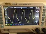
I am using PWM and its complement at 20kHz to drive an HIP4082 Mosfet Driver and H-Bridge made out of IRF3205 Mosfets. The output then feeds a common mode choke followed by a 12V to 240VAC, 225VA toroidal transformer. I then have a 4.7uF, 300V capacitor on the output of the transformer. So far it is working very well. It is producing a nice clean sine wave with no load and minimal distortion when running 2 * 40W fans. However, i am in the process of added output voltage regulation which i am trying to achieve via reducing the PWM values. I have 15 different tables, 100%, 97.5% ... 62.5% reduction of the PWM values that generate the sine wave. During testing today I found that these reduced value tables were creating significant distortions on part of the sine wave. See picture which is using the 90% table. Testing with one table at a time until i get it right. The distortion would would start even with 97.5% table and become more pronounced as i used a further reduced value table. The idea came from here: https://tahmidmc.blogspot.com.au/2012/11/feedback-in-sine-wave-inverter-pic16f.html. I however am using an 800 value table full wave table.
I have tried the following:
- A variety of different value inductors on the output of the H-Bridge, before the transformer. 33uH through to 470 uH. This just helps smooth the distortion to some extent.
- A variety of capacitors on the output of the transformer. .33uF trough to 4.7uF. Smooths the small ripple caused by the PWM duty change as it creates the wave.
- Changed the dead time on the HIP4082 (15K and 33K ohm resistors). Nothing happened.
- Verified the value table is correct. I.e. the 90% is the 100 percent value table * 0.9 (calculated in excel). I have double checked the values and using a 10K resistor and .1uF ceramic confirm it creates a nice clean sine wave at least before it goes to the HIP4082. See the third attached picture of the PWM passed through a 10K & 0.1uF cap for. Note, small variations in amplitude are due to using two different scope probes unfortunately.
- Lowered the gate resistors on the Mosfet from 33 ohms to 16.5 ohms (2 in parallel). No change.
Other observations: a noticeable buzzing comes from the transformer when the distorted wave form is observed. No load current rises form 0.7A @ 19VDC to 4.1A @ 19VDC when the distortion is apparent (90%). Applying a load does not assist.
The second attached file is the output of the transformer (via a 24V step down transformer) when the PWM table of 100% is used. The circuit design is almost identical to that in the HIP4082 datasheet.
Thank you for your help and suggestions.


Last edited:

