Continue to Site
Follow along with the video below to see how to install our site as a web app on your home screen.
Note: This feature may not be available in some browsers.
Can anyone help me in plotting the overall transconductance of an OTA (Gm) circuit in cadence step by step.
Do I have to do the ac analsis or DC analysis?
The transconductance gm is a small-signal parameter. Hence, we need a small-signal analysis - that means: AC analysis.
However, gm depens on the bias current (Iabc) and - of course - also on frequency.
Therefore, for answering your question, we need to know what you want: gm=f(f) or gm=f(Iabc)?
.jpg")
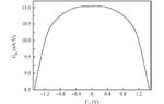
I want to calculate the transconductance vs vid to check the linearity.I think I need gm f(Iabc). I want to calculate gm=Iout/(V+-V-) i.e. gm=Iout/Vid vs Vid.
I hope you can understand for your convinience I am attaching a graph. I want to plot this graph.
View attachment 134679
How can I plot this graph gm vs vid in cadence.Please can you tell me step by step process of this plot.

Thanx for your reply. I want to know what dc value to I have to place at the output (vdc)? Can it be any value?
What is the purpose of the DC source at the output?
It has - most probably - the task to measure the output current. Some simulation programs require such a source for measuring currents.
Hence, it must be, of course, a zero Volt source (VDC=0)
why do we have to do dc sweep? why not ac sweep vid is ac.
No. It wont be zero volt source. In order to have same conditions you have to set it to your output dc level.
- - - Updated - - -
How can you find gm with ac sweep when your vid is constant and your frequency is changing ???
gm = delta (Id) / delta (vid)
think about it.
Don't see this difference between vid and vd anywhere in your previous posts. LvW used vd instead vid in one post, without a particular intention as far as I see.vid is a ac signal. Vd is the dc bias.
I want to plot this curve attached.
I am using cadence. I am a bit confused. vid is a ac signal. Vd is the dc bias. You are saying sweeP vid. When vid is an ac signal it means we have to do ac sweep. Am I right?
")