Continue to Site

Welcome to EDAboard.com

Welcome to our site! EDAboard.com is an international Electronics Discussion Forum focused on EDA software, circuits, schematics, books, theory, papers, asic, pld, 8051, DSP, Network, RF, Analog Design, PCB, Service Manuals... and a whole lot more! To participate you need to register. Registration is free. Click here to register now.

12v NiMH UPS for adsl router and computer schematic needed

Status
Not open for further replies.

neazoi

Advanced Member level 6
Joined
Jan 5, 2008
Messages
4,123
Helped
13
Reputation
26
Reaction score
15
Trophy points
1,318
Location
Greece
Activity points
36,955
Hello,
I have an adsl router at home (like most) and a small computer (mini server) connected to it.
The computer is an Alix-1D and consumes only 5W max at 12V.

I want to build a small UPS for these two, so that it can keep them up and running when power is lost. Mostly interested in sudden power loss, a few minutes max (which happens oftenly) and not long time power loss. Note, only 12v DC output is needed, not conversion to 220v AC.

I want to use 10 low self discharge AA NiMH batteries connected in series to produce about 12v, just what the computer and the router needs.

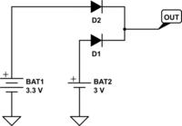
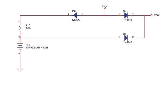
A simple UPS can be as simple as this one
with two diodes.


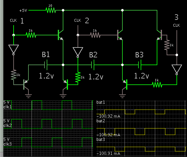
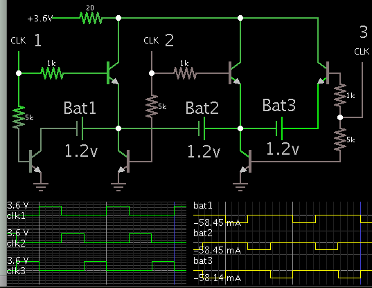
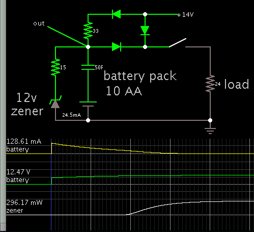
However this does not charge the batteries, so I need a circuit to charge these 10 NiMH batteries connected in series. I need this circuit to be safe, not exploding the batteries, as it is for home use. So something like this


[found at www .electronics -circuits .com /schematics /embedded /battery -backup .png[/url]

is not good probably as will overcharge the batteries or even damage them.

I cannot find any such circuit on the net, all I have found refer to single batteries or pair, not 10 in series.

Some help is appreciated.
 
Last edited by a moderator:

One option is a charger that stops when the battery pack reaches 12 or 13V. To start charging again, the voltage must drop to 10 or 11V. This might be done with a window comparator consisting of two op amps (or one op amp with hysteresis). The op amps drive a transistor or mosfet.

Or a charger that is simply regulated to 12.5 V. The battery pack only goes that high and no higher. Install an inline resistor (or biased transistor), whose current is adjusted to deliver safe charge rate. In fact a simple zener regulator might be sufficient. It depends on how quickly you want to charge the batteries, and how often a blackout hits. It also depends on the supply voltage. The zener diode idea could be adapted to your schematic #2. It is feasible to put a resistor inline with the zener, to reduce accidental overmuch current through it.
 
  • Like
Reactions: neazoi

    neazoi

    Points: 2
    Helpful Answer Positive Rating
One option is a charger that stops when the battery pack reaches 12 or 13V. To start charging again, the voltage must drop to 10 or 11V. This might be done with a window comparator consisting of two op amps (or one op amp with hysteresis). The op amps drive a transistor or mosfet.

Or a charger that is simply regulated to 12.5 V. The battery pack only goes that high and no higher. Install an inline resistor (or biased transistor), whose current is adjusted to deliver safe charge rate. In fact a simple zener regulator might be sufficient. It depends on how quickly you want to charge the batteries, and how often a blackout hits. It also depends on the supply voltage. The zener diode idea could be adapted to your schematic #2. It is feasible to put a resistor inline with the zener, to reduce accidental overmuch current through it.

So is it enough to connect the zener (in series with a series resistor) in the second schematic in parallel to the battery? Would that really be that simple?
Note, the batteries are NiMH not NiCD as shown in the schematic. And they are 10x1.2V in series.
 

So is it enough to connect the zener (in series with a series resistor) in the second schematic in parallel to the battery?

This is feasible only if we're talking about a power supply which is not much greater than 12V. That allows you to use low ohm resistors, and possibly a low-Watt zener.

We add the zener diode to your schematic #2:

8430243100_1481566745.png


The simulated battery pack consists of a voltage source and capacitor. Notice the battery pack begins at 9V. As it reaches 12V the zener draws away excess current.

Real zener diodes can be off-spec. You need to experiment with values, in order to find the best voltage for maintaining your battery pack. It's a question of what voltage is optimum (whether 12V or 12.5 or 13, etc.). In other words, what is your battery's resting voltage in a full state of charge? It's hard to be sure.
 
  • Like
Reactions: neazoi

    neazoi

    Points: 2
    Helpful Answer Positive Rating
This is feasible only if we're talking about a power supply which is not much greater than 12V. That allows you to use low ohm resistors, and possibly a low-Watt zener.

We add the zener diode to your schematic #2:

8430243100_1481566745.png


The simulated battery pack consists of a voltage source and capacitor. Notice the battery pack begins at 9V. As it reaches 12V the zener draws away excess current.

Real zener diodes can be off-spec. You need to experiment with values, in order to find the best voltage for maintaining your battery pack. It's a question of what voltage is optimum (whether 12V or 12.5 or 13, etc.). In other words, what is your battery's resting voltage in a full state of charge? It's hard to be sure.

Thanks for the simulation!
Ok I see you have an input voltage of 14v, obviously to compensate for the diodes drop. I could include a small lm317 regulator to supply this voltage, maybe this will be adequate.
What is the charging current for the batteries with this 33R, is it 128mA? Maybe one could do this less to prevent overheating of the batteries, as no fast charging is needed. Any estimation for other values of resistors?
Do you think that it would be quite safe to build this, in the sense that the ups will be left unattended in a closed room for months maybe.
I do not want the batteries to blow up or leak, this would be quite a disaster and make things messy to clean from all these chemicals!

PS. I have some 2.7V 400F supercaps. What if I connect 5 of them in series and charge them up to 2.4v? It would have a total cap of 80F, more than your simulation for the battery. maybe they could cope with the power failures for quite a few minutes, without even need replacing! However they are much more expensive :) There are some ballancing boards sold on ebay. Just an idea...
 
Last edited:

Thanks for the simulation!
Ok I see you have an input voltage of 14v, obviously to compensate for the diodes drop. I could include a small lm317 regulator to supply this voltage, maybe this will be adequate.

Right, if you regulate initial supply voltage, then you don't need the zener regulation. Simply adjust the 317 output so you get the desired voltage reaching the battery pack (after the steering diode subtracts 0.6 V).

What is the charging current for the batteries with this 33R, is it 128mA? Maybe one could do this less to prevent overheating of the batteries, as no fast charging is needed. Any estimation for other values of resistors?

You can increase the resistor to charge at lower rate. It may be satisfactory. You need to try your own simulations. Or better yet, run tests on hardware.

Do you think that it would be quite safe to build this, in the sense that the ups will be left unattended in a closed room for months maybe.

My schematic is not a 'smart charger'. Everything about this project must be custom designed. It ought to be tested in various conditions. Volt and Ampere levels need to cooperate so you don't burn up anything.

It's a stiff requirement, to manage voltage tolerances for all components so that:

(a) Your power supply is at the correct voltage to run the modem.
(b) And it is at the correct voltage to charge the batteries.
(c) And the batteries are maintained at the correct voltage to run the modem.
(d) And diodes each subtract a certain voltage drop.

I do not want the batteries to blow up or leak, this would be quite a disaster and make things messy to clean from all these chemicals!

It's wise to check battery condition every month or so. Check each one individually. If any battery goes bad, then you want it to notify you with some kind of alert. That is a whole 'nother project, to detect if a battery goes short circuit, or cannot hold a charge, etc. This can be hazard to all the batteries. If any one of them goes short circuit, then it causes the pack's voltage to drop by 1.2V. The entire pack resumes charging, at a rate which may be unhealthy for fully charged batteries if allowed to continue indefinitely. Thus you could end up with every battery ruined.

If you plan to let the battery pack go months without maintenance, then you should consider getting a smart charger, designed for a 12V nimh battery pack.

PS. I have some 2.7V 400F supercaps. What if I connect 5 of them in series and charge them up to 2.4v?

Charging a series stack of capacitors is uncertain. They may have slightly different Farad values, and they may start out at unpredictable volt levels. Thus they may reach unequal volt levels by the end. A resistive divider can balance the volt levels. This is an area for experimentation.
 
  • Like
Reactions: neazoi

    neazoi

    Points: 2
    Helpful Answer Positive Rating
If you plan to let the battery pack go months without maintenance, then you should consider getting a smart charger, designed for a 12V nimh battery pack.

Thanks for all this info!
Exactly that was what I suspected, I could not imagine that these simple circuits could do this without damaging the batteries.
A crazy idea I was once thinking, was to use one of these 1.2v smart chargers (already have one) and connect the batteries in parallel (one on each charging slot). Then use relays to connect them in series when all of them are charged. Idiot, but it could work. However you would have to wait for the batteries to get charged and you would not have a UPS then.

Or you could make this idea simpler for a more real UPS. You could have an extra battery and charge it in this smart charger, then when charged, insert it in series with the other (partially discharged) batteries and pull out the next one to charge. This solution might be more feasible, since there is usually some voltage tollerance in the routers (they can operate 1.2V lower on higher). I do not think it matters too much for one battery to be more charged than the others in a series multi cell, or does it?
In simple words, you continuously pull one battery in and out and charge it, then you reinsert it in series with the others and pick up the next one for charging. some clever relay switching has to be thought, but I have many miniature dip relays. The charged state could be taken from a feedback from the charger LED indicator. How do you find this last idea?
 
Last edited:

I've been exploring the abilities of H-bridges and half-bridges. By turning transistors on and off in sequence, you can charge each cell, one at a time. This should also provide a means for you to to read its voltage and charge rate.

Switching can be done by a 4017 IC (decade counter), since you have 10 cells. My supply voltage is 5V because the inverter gates are fixed at 5V. You need to adjust values to work with your power supply.

I tried simulations with various arrangements of NPN and PNP. This schematic seemed to work properly.


There may be an easy way to gauge battery health. I tried measuring voltage on my AA batteries as they charged. Typical value is 1.5 to 1.8V for a healthy cell. If it has developed high internal resistance then it causes a higher voltage. If it has gone short circuit then its voltage stays near zero.

Experiment with your rechargeables to find out what volt levels they assume during a charge. If any cell reads abnormal, then it causes an alarm circuit to light an led, or sound an alert, etc.

There is the case where a cell is able to take a charge, and to power a load, but not for long. This type of deterioration easily goes unnoticed. A 'really smart' charger would need to check whether the battery can provide power for a certain length of time.
 
  • Like
Reactions: neazoi

    neazoi

    Points: 2
    Helpful Answer Positive Rating
I've been exploring the abilities of H-bridges and half-bridges. By turning transistors on and off in sequence, you can charge each cell, one at a time. This should also provide a means for you to to read its voltage and charge rate.

Switching can be done by a 4017 IC (decade counter), since you have 10 cells. My supply voltage is 5V because the inverter gates are fixed at 5V. You need to adjust values to work with your power supply.

I tried simulations with various arrangements of NPN and PNP. This schematic seemed to work properly.


Thanks!
I am sure this schematic has something ingenious in it, but I need to ask a few things.

1. Are the batteries charged fully one at a time, or does the charging takes place in sequence with one pulse for each battery (i.e. one charge pulse for battery B1, then go to the next battery B2 and send one pulse, then B3 and so on, untill all batteries are charged simultaneously.

2. Can I connect the load at B1+ and B2- and leave this charging circuit connected as well?

3. The inverter gates are 5v, but what should the VCC be 12v or 1.2v? Also, since the output of the inverters is 5v, shouldn't I redice it to 1.2v (with a simple voltage divider maybe)?
 

Thanks!
I am sure this schematic has something ingenious in it, but I need to ask a few things.

1. Are the batteries charged fully one at a time, or does the charging takes place in sequence with one pulse for each battery (i.e. one charge pulse for battery B1, then go to the next battery B2 and send one pulse, then B3 and so on, untill all batteries are charged simultaneously.

Ideally you should charge the batteries, then leave them be. Continued charging is risky.
Monitor the pack's voltage, and when it drops below nominal, initiate a charging/checking session for all the batteries.

Or as an alternative it's probably okay to give them 50 or 100 mA for a minute each day. Check each one's voltage. Do a short test to see if it can power a load.

2. Can I connect the load at B1+ and B2- and leave this charging circuit connected as well?

It appears the battery pack must be disconnected from the load and power supply (from what my simulation indicates).
This may be an instance where your relays are necessary to the project.

3. The inverter gates are 5v, but what should the VCC be 12v or 1.2v? Also, since the output of the inverters is 5v, shouldn't I redice it to 1.2v (with a simple voltage divider maybe)?

NPN's could be all you need, provided the power supply is a high enough voltage, and that it supplies sufficient current.


Naturally it requires further testing for all conditions. Load attached/ detached. Supply attached/ detached. Etc. One problem that easily occurs is, that the middle battery tries to discharge through any path it can find, resulting in undesired current flow in the wrong direction. Steps must be taken to prevent it.

The aim is to find the right combination of NPN, PNP, taking bias from various points, etc.

As you can see, a backup power supply takes work to design and construct.
 
  • Like
Reactions: neazoi

    neazoi

    Points: 2
    Helpful Answer Positive Rating
Status
Not open for further replies.

Similar threads

Part and Inventory Search

Welcome to EDABoard.com

Sponsor

Back
Top