Continue to Site

Welcome to EDAboard.com

Welcome to our site! EDAboard.com is an international Electronics Discussion Forum focused on EDA software, circuits, schematics, books, theory, papers, asic, pld, 8051, DSP, Network, RF, Analog Design, PCB, Service Manuals... and a whole lot more! To participate you need to register. Registration is free. Click here to register now.

[General] Analog Output interfacing with 5v microcontroller

Status
Not open for further replies.

Sandeep.Lerio

Junior Member level 1
Joined
Dec 5, 2016
Messages
16
Helped
0
Reputation
0
Reaction score
0
Trophy points
1
Activity points
126
Hello Everyone,

This is my first post on this forum., Seems like there are a lot of rules in this forum.

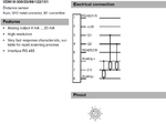
I have an analog output is 4-20mA industrial distance sensor. And I would like to interface the analog output of this sensor to a 5V microcontroller.

Normally a 250Ω resistor is used to get 1 to 5V measured across the resistor, but at this point, I'm not sure how this would connect to an Arduino because I don't know if analog- can be connected to Arduino GND.

I guess if I just connect the grounds together, and use something around 620Ω across analog+ and analog-. I'm getting about 10V swing (-5V to +5V) ... but the max resistance allowed in the specifications is <=500Ω.

Is there any way to connect analog output to 5v microcontroller? I attached the datasheet of the sensor, Please have a look let me know what you think about it :)

#sorry if this forum is not apporiate for this question.
 

Attachments

  • 193924_eng-Datasheet.pdf
    346.8 KB · Views: 128

You can't measure AC using ADC of MCU. You need to convert it to DC and scale it to 0 to 5V range for ADC. As your signal is very low you can Level Shift the AC signal by adding a proper DC voltage and then scale it for adc.
 

Hello Okada,

Thanks for reply. Yes, I check the voltage across 4-20mA output and It varies -22.34v to 22.34v. So, I Normally add 250Ω resistor used to get 1 to 5V measured across the resistor, but at this point, I'm not sure how this would connect to an Arduino because I don't know if analog- can be connected to Arduino GND.

I guess if I just connect the grounds together, and use something around 620Ω across analog+ and analog-. I'm getting about 10V swing (-5V to +5V) ... but the max resistance allowed in the specifications is <=500Ω.


Let me know what you think about it
 

Show your exact circuit.
 

Hi,

@Sandeep.Lerio

Without rules... there will be chaos ;-)

I'm not sure how this would connect to an Arduino because I don't know if analog- can be connected to Arduino GND.
We don´t know this either.
But you have the circuit and the sensor informations. Only you can tell.
--> give us the circuit the sensor name and best if you can give use links to the datasheets also.

I'm getting about 10V swing (-5V to +5V)
Where does the negative voltage come from?

*****
@Okada
You can't measure AC using ADC of MCU.
For sure one can measure AC using ADC of MCU.
One can not measure negative voltages directely. But 4..20mA is not negative.

Klaus
 
  • Like
Reactions: Okada

    Okada

    Points: 2
    Helpful Answer Positive Rating
Hi,

The datasheet is very uninformative. As far as I understood, analog+ and analog- are the output for your sensor and you need to measure and digitize the voltage across them.

You can connect the analog+ output to ADC pin of MCU, however you cannot directly connect -analog to ADC pin, because you need to connect the sensor GND and MCU GND and connecting them through resistor will not help, you are just running some current between ADC and GND.

I faced a similar problem before, so I suggest using an inverting amplifier in between the analog- output and ADC pin of the MCU. Here, you need to use two ADC pins, one for analog+, one for analog-. Then you can add the values you measure from ADC#1 and ADC#2 in the software to obtain the correct result.
 

Hi Ogulcan,

Thanks for reply.I apologize for insufficient information on the data. I added manual and datasheet,
Please have a look and tell me your suggesstions.

I'm using Industrial distance sensor with analog ouput 4 - 20 mA. What I'm trying to do is just interface Arduino Uno with Industrial Laser sensor. As you know its 5v microcontroller, And sensor output range -22.34V to 22.34V (for 80mm-300mm distance).
 

Hi,

The datasheet is very uninformative.
I agree with this.

But to measure the voltage across analog+ and analog- ... I don´t think this makes sense, since it is a current output.

***
Often 4..20mA interfaces are simple current sinks, but it may be a true current source.
And: It may be isolated, or not. (If isolated, then what max isolation voltage?)

Both is not clear from reading the datasheet.

I think there is no way around contacting the manufacturer.


Klaus
 

Even the full product manual doesn't manage to explain the internal connection of Analog+ and Analog- terminals. https://files.pepperl-fuchs.com/selector_files/navi/productInfo/doct/tdoct1314a_eng.pdf

You'll either figure it out yourself, ask Pepperl&Fuchs support or stay with an isolated power supply.

I check the voltage across 4-20mA output and It varies -22.34v to 22.34v.
Makes no sense. 4-20 mA interface is always unipolar DC. What do you exactly mean with "voltage across"? A meaningful test would be to connect a shunt and measure the voltage between Analog- and 0V, also measure the resistance, the output might be even isolated.
 

But to measure the voltage across analog+ and analog- ... I don´t think this makes sense, since it is a current output.

That's right I forgot to mention that he also needs a trans-impedance amplifier just after the analog- output.
 

Don't see a reasonable purpose of a transimpedance amplifier without further information. It's no usual function in industrial measurement and automation. The sensor must be expected to work with industry standard analog IO, e.g. PLC analog inputs which use shunts for current measurement. Open question is about possible need for isolation against DC power supply.
 

hi ,
i had similar problem with ultrasonic sensor used to measure width (layflat) of a material , in the and i used a 741 opamp as current to voltage converter . Actually i amplified the voltage drop on a resistor , by adjusting the gain on the 741 i managed to bring the level to 5V at full scale
 

Thanks for reply everyone,

I attached the wiring and more information. Please have a look and suggest me your views about it:bsdetector:
 

Attachments

  • Doc 1.pdf
    713.9 KB · Views: 131

The measurements suggest an internal connection between 0V and Qa-. It should be repeated with a 100 to 500 ohm load resistor at Q+/Qa-.
 

The measurements suggest an internal connection between 0V and Qa-. It should be repeated with a 100 to 500 ohm load resistor at Q+/Qa-.


Sorry about Novice knowledge on electrical wiring. Are you sure it required an internal connection between "0V and Qa-" . Please see the attached picture and let me know about it. Wiring 1.png
 

Hello Everyone,


I'm trying to get 4-20mA current analog output reading from the Pepperl+fuchs VDM 18-300 which PNP connection type. But I'm not getting. Do you know why?
 

For curiosity i would try to measure voltage between pin 6 and pin 7 , maybe on 470 ohm resistor connected between those pins .
With Arduino you can select some internal reference of 1.2 V... so you should be able to use it directly .
 

Attachments

  • Circuit.png
    Circuit.png
    50.9 KB · Views: 107
  • Circuit 1.png
    Circuit 1.png
    39.6 KB · Views: 145
  • RS232-RS485.png
    RS232-RS485.png
    126.1 KB · Views: 162

Status
Not open for further replies.

Similar threads

Part and Inventory Search

Welcome to EDABoard.com

Sponsor

Back
Top