nosnos
Newbie level 1
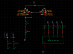
I have a current mirror of 5 transistors with wf=500n, L=200n, nf =2 --> this is the size of the unit.
I'm trying several patterns configurations for these transistors and every time i get the ID mismatch between the layout and the schematic. I'm doing this study on patterns having dummies only on left and right sides. But some patterns i find fingers on the edge in region 3.
The patterns having this issue some are solved by increasing the side dummies sizes and others the case get worse on increasing he side dummies. Does any one have an explanation for that?
The other question: why Vgs changes from one pattern to another?
kindly find attached the Test bench and the schematic values.

