gonespa
Member level 1
Hi,
I am experimenting with a half bridge built arount the IR2110. When trying to determine the turn-on/turn-off times by using an oscilloscope and changing the values of the gate resistor, I found a weird problem:
As I reduce the gate resitor value I observe that the turn-on time decreases, as expected. Turn-off time is however aprox. equal or marginally lower in each test.
I know turn-off takes more time than turn-on, provided the gate capacitance discharge path is the same, so I tried paralleling a diode (an ultra fast one) so that discharge is channeled through it. I don´t observe any improvement, and I can´t understand where might be the problem, can anybody provide some clues??
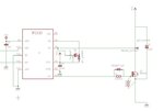
The test circuit is attached. My dummy load is missing. It is a series 1k resistor and green led connected from "PHASE OUTPUT" to VCC (which is aprox. 10V). The high side MOSFET is ommited too, but it is in place, permanently off, severing the link between VCC and PHASE OUTPUT
There is an MCU connecter to it providing a PWM pulse at 2Khz, 50% duty cycle.
I attached the oscilloscope screenshots using 220 Ohm and 83 Ohm examples as well as the diode in place. I measured voltage between the leads of the diode too in another screenshot.
Channel 2 is the voltage between circuit ground and the MOSFET drain.


