neazoi
Advanced Member level 6
Hi, I want to build a simple lab PSU with the LT3080. I have two of these regulators plus a multitap transformer, taken out from a commercial LM317 PSU. I need the whole PSU to be very small in size, smallest possible, but not SMPSU.
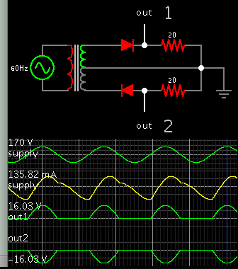
My proposed schematic is attached. Note that the Vcontrol is connected to the input, for simplicity. To limit the heat (and thus the size of the heatsink), I use the multitap transformer in combination with a selector switch, to select the right range.
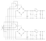
There are two PSUs conencted in parallel to the transformer. Of course the transformer max current is shared between them.
1. Can I connect the GND of the first PSU with the positive out of the second to build a symmetrical PSU (I am not sure if this IC will have any problems connected like this)?
2. On page 18 of the datasheet a LAB supply is shown which has also current limiting. But it can go only up to 10V. Since my transformer can output max 15V, can I somehow alter this circuit so it can at least go to 12V current limited? MAybe by changing the value of set resistors or connect the Vcontrol pin of the second IC somewhere else?
My proposed schematic is attached. Note that the Vcontrol is connected to the input, for simplicity. To limit the heat (and thus the size of the heatsink), I use the multitap transformer in combination with a selector switch, to select the right range.
There are two PSUs conencted in parallel to the transformer. Of course the transformer max current is shared between them.
1. Can I connect the GND of the first PSU with the positive out of the second to build a symmetrical PSU (I am not sure if this IC will have any problems connected like this)?
2. On page 18 of the datasheet a LAB supply is shown which has also current limiting. But it can go only up to 10V. Since my transformer can output max 15V, can I somehow alter this circuit so it can at least go to 12V current limited? MAybe by changing the value of set resistors or connect the Vcontrol pin of the second IC somewhere else?
Attachments
Last edited: