Welcome to our site! EDAboard.com is an international Electronics Discussion Forum focused on EDA software, circuits, schematics, books, theory, papers, asic, pld, 8051, DSP, Network, RF, Analog Design, PCB, Service Manuals... and a whole lot more! To participate you need to register. Registration is free. Click here to register now.
The 51 Ohm resistor could well be 50 Ohms anyway. a 10% tolerance is likely to vary from at least 45 to 55 Ohms anyway so you are not likely to gain anything
same for your 27 Ohm resistor .... I personally haven't seen 25 Ohm resistors ... there may be one of the lesser known E series that has a 25 Ohm
maybe ideally, but in the real world it isn't likely to happen
consider you have only been looking at the resistor values. What about the tolerances of the inductors and capacitors ?
they will affect the outcome as well. Living with acceptable tolerances is what it is all about
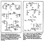
I see two 27 Ohms in series at the input... making 54 Ohms. Then there is a connection between both of them... decreasing overall input impedance a bit.
Is it really far away from 50 Ohms?
I´m talking about circuit "C", left side of picture. OP says "3rd diagram".
I see two 27 Ohms in series at the input... making 54 Ohms. Then there is a connection between both of them... decreasing overall input impedance a bit.
Is it really far away from 50 Ohms?
I´m talking about circuit "C", left side of picture. OP says "3rd diagram".
Can you please tell me If I can connect the 10nF capacitor of circuit A, to the same place on circuit B (shunt between the diode and the choke)?
Will it affect the performance of circuit B in a negative manner?
This site uses cookies to help personalise content, tailor your experience and to keep you logged in if you register.
By continuing to use this site, you are consenting to our use of cookies.