Continue to Site

Welcome to EDAboard.com

Welcome to our site! EDAboard.com is an international Electronics Discussion Forum focused on EDA software, circuits, schematics, books, theory, papers, asic, pld, 8051, DSP, Network, RF, Analog Design, PCB, Service Manuals... and a whole lot more! To participate you need to register. Registration is free. Click here to register now.

Solar battery charger: buck VS boost

Status
Not open for further replies.

kathmandu

Full Member level 5
Joined
Dec 7, 2015
Messages
298
Helped
7
Reputation
14
Reaction score
7
Trophy points
18
Activity points
3,146
Hello,

I want to redesign my solar off-grid network by reconfiguring the PV panels (series/parallel) and by building a high efficiency battery charge controller.

Speaking of battery chargers, the buck converter seems to be the obvious (and most used) circuit topology but, when it comes to active components (mosfets) selection, I found it hard to get a high Vds, high current and low Rdson ones.

By comparison, both buck and boost switches must have the same current rating (dictated by the maximum inductor current) but the one used in a boost topology has a much lower Vds stress hence it's easier to source a low Rdson one.

Another circuit trivia is to isolate the solar source (PV panels) from the battery when the sun is OFF. A buck topology can't do that by default so you may need an extra switch (thus extra loses) to accomplish that.

As I could place the charge controller very close to the PV panels (hence wire loses are not a problem), do you think it's a better idea to use a boost topology instead? (low Vds / low Rdson mosfets)

By the way, the battery bank voltage is 48V and I have 12 x 230W PV panels installed for now (Voc = 36V, Isc = 8A).
 

Hi,

"buck" or "boost" depends on input and output voltage:
--> If your desired output voltage is higher than the input voltage then use "boost".
--> If your desired output voltage is lower than the input voltage then use "buck".

Klaus
 

Thanks for your reply, @Klaus. Like I've just said, the output should be 48VDC but I could set the input anywhere between 30VDC to 360VDC.

My question was if it's better to use a low voltage input / boost converter or a high voltage input / buck converter for all those reasons I've mentioned in the previous mesage.
 

Hi,

usually with power transmission one wants high voltage for low loss with thin cabling.

Some calculations:
12 panels can be configured:
* 12S, 432V, 8A
* 2P6S, 216V, 16A
* 3P4S, 144V, 24A
* 4P3S, 108V, 32A
* 6P2S, 72V, 48A
* 12P, 36V, 96A
(You could have made the table by yourself)

So it´s a kind of taste, available components and safety.

I´d say working with currents of 32A and below is no problem.
And I´d say working with voltages of 216V and below is good. But still dangerous.

I tend to 3P4S (or 4P3S). Finding Mosfet´s and their power dissipation shouldn´t be the problem.

Klaus
 
Thank you for the detailed calculation but I'm afraid you still don't get my point.

I was just saying that whenever you're using a buck or a boost topogy, the switch (mosfet) must be rated at inductor maximum current.

As the conduction loses are Rdson * Id^2, it's hard to find a low Rdson high voltage mosfet.

And there is the other limitation of a buck converter: the lack of isolation from output to input when the input voltage falls under the output voltage level (and that's happening when tbe PV panels are sitting in the dark).

The only advantage of a higher input voltage is the reduced wire loses but, like I've just said, the charger (and the batteries) are close to PV panels hence wire loses are negligible.

Btw, another advantage of a boost converter is the continuous input current, which is a good thing for the PV panels (and I could use a smaller capacitor bank at the charger input).
 

I decided to use the buck boost circuit topology in my system. I know it requires an even higher voltage rated mosfet, and its not what you want.
But I will give my reasons.

My solar panels provide a negative voltage with respect to ground. The output of the buck boost converter being positive. This has a few advantages.

The switching mosfet can be N type with the source at a steady dc voltage which makes the mosfet very easy to drive direct from the control chip.

The output voltage can be above or below, (or pass through) the input voltage, so it can either raise or lower the voltage from the solar panels. This gives great freedom if you later decide to change the system voltages on either side.

You may like to consider possible failure modes, and the buck boost topology if it fails, the output always drops to zero. A shorted buck regulator could potentially create a destructive down stream over voltage, which may be expensive.

The most efficient design would probably be where the input and output voltages are approximately in the same voltage range. In your case two 24v panel banks in series for a 48v system.

So something like 72 volts open circuit, (60 volts MPPT) on the input side, at a bit less than 48 amps.

That's just a bit short of 3Kw. I have three 2Kw buck boost converters in paralell.
I think I would split your system into two groups of panels and run two 1.5 Kw controllers. It adds a bit of redundancy, and you only have to shut down half the system to work on the other half.

- - - Updated - - -

****update****

Some further thoughts.
If you run a boost topology, you will need to run all your twelve panels in parallel, and that requires switching close to 100 amps.

Buck boost topology you can double the input voltage, and only have to switch half the current, which will be a lot more efficient.

Buck topology is not recommended because a controller failure may fry your battery or inverter.
 
Last edited:
Hi,

I'm afraid you still don't get my point.
I agree.

On the other side you give no calculations. A simple excel chart will give true results instead of weak pro and contra thoughts.

Example: buck, 144V input, 48V output, 3kW.
Duty cycle: about 33%. Max switching current 90A. (Estimated)
If you now choose a 20mOhms Mosfet, then you get about 55W conduction loss. Sounds not bad.

Now play with various voltages, various frequencies, multiple Mosfets (maybe polyphase to reduce input and output capacitors)
Too see which one best fits to your needs.

Klaus
 
Thank you very much, @warpspeed!

As always, I'm saving all your posts as "application notes" for further reference!

What can I say, I've thought about using a full bridge (boost-buck) topology but I wanted to avoid the increasing number of switches.

Btw, for now I'm using an "emergency" charger (as the old commercial one had some problems). That's it, the PV panels are connected right across the battery bank (in pairs of two, of course) and I'm using some relays to "regulate" the charge current, by switching on/off a corresponding number of PV pairs.

Speaking of that, I've noticed some particular behaviour (well, it might be logical) of this "emergency charger" during cloudy/grey sky periods: the output power of the PV is very small (like 3-5% of the rated power).

It might be that because the PV voltage are way bellow the battery voltage (I have 60 cells panels, not 72). Anyway, I used to have just a little bit better results with my former commercial charger (proudly labeled as MPPT) which leads me to the conclusion that it was a dumb PWM one.

Btw, I've used the same panel configuration (30V + 30V) before.

From your own experience, what was the minimum output power of the PV panels during sun "blackout"? There is some more power in that diffused light? (more than 3-5%, that is)

Back to the charger topology: I was not afraid of charger failing as the PV panels are limited current sources hence they should adapt to the "after death" situation. That's it, they will withstand open or short circuits as well.

But, taking into account your valuable arguments, I guess I'll choose the buck-boost topology, indeed.

One further advantage: I could switch to my "emergency charger" at any time, as the panels should remain in this current configuration (pairs of two).

Once again, thank you very much for your time and for sharing your knowledge. Btw, you should write a book sometime.. a huge one! ;)


@Klaus:

Sorry, it was my fault. I was not asking for the calculations (at least, I thought I didn't) but the advantages of one topology over another (buck/boost).

Anyway, I've did some preliminary calculation too but the best compromise (mosfet voltage/current/Rdson ratings) was for an input voltage of 60V, but that was exceeding the allowable limits for both buck or boost topologies alone.

But the answer was supposed to be that simple: a buck-boost topology.
 
Last edited:

From your own experience, what was the minimum output power of the PV panels during sun "blackout"? There is some more power in that diffused light? (more than 3-5%, that is)
I have my panels arranged in three separate groups, pointing in four completely different directions, feeding three individual MPPT controllers.

One set of panels faces north with a very low angle of panel elevation (20deg) that is "looking" almost straight up.
And that always produces the most output when the sky is a totally even forbidding grey of only diffused light. The output is very low, only a few percent, but it still beats the other arrays in such awful conditions.

For collecting only very dim diffused light, a horizontal panel which can "see" the horizon all the way around might theoretically be optimum, but its just not practical.

I am beginning to think that the best solution to all this might be to grossly overpower the system with excess solar panels, and just fit a smaller current limited controller that is only big enough to supply actual daily needs.

Just because you have 100 amps worth of panels (or whatever) does not mean you absolutely must build a 100 amp capable controller. In winter on many days you might be getting much less, and that might be quite sufficient in summer as well.

I now have over 6Kw of panels installed, no battery as yet, and an 1800 watt inverter which works fine.
I have not run it through winter yet, but I expect to still be able to get several hundred watts even under the worst conditions. We shall see.
 
I'm living off-grid hence, for me, the "yearly average output" it's useless. As I rely on batteries only, every single watt counts.

Anyway, lead-acid batteries are very lazy thus they need TIME to reach the full charge. Even my smaller PV array it's useless during winter season as the total available charging time is too small. You need maybe 6-8 hours for topping charge (low current, constant voltage) but that's the full available daylight time.

The bulk charging ends up usually way before noon (thus all the full power request ends here) but I couldn't reach the 100% state of charge on the few daylight hours that remains.

That's why I have decided some times ago to keep the existing PV array and build a wind turbine. That way, the charging time is virtually unlimited (at least, you can expect some wind harvesting during the night but no sun!).
 

That is true.
In winter battery capacity is everything when off grid, and lead acid batteries are less than perfect, requiring very long recharge period to restore full capacity.

My situation is very different, I am on grid and just wish to reduce my power bills.
For me, a battery is just not cost effective.
I just need to supply some low average power for most loads during the day only, and I can pull high surge current from the grid during the day if needed, and run completely with grid power at night.

Wind power will be an excellent supplement if you can do that.

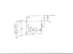
Here is some very basic buck boost topology for a 48v/48v system.
buckboost.jpeg
 

Actuay, the (updated) wind turbine will be up & runnig in few days. I had a smaller one (300W) in the past but now I made a much bigger one (the alternator is rated at 3kW but I'm expecting a peak of 2-2.5kW in high winds).

I also found a better (windy) location thus my batteries should feel happy. My average daily consumption is around 5-6kWh hence an average hourly wind power of 200Wh could by-pass the PV panels entirely.

- - - Updated - - -

That schematic looks very interesting but I need to implement a MPPT algoritm hence I thought of a full bridge driven by a microcontrolller.
 
Last edited:

That is going to make a HUGE difference.

Just to give you an idea, my daily consumption at this time of year over the last few years (before solar) has been in the 4 to 4.5 Kwh per day range.
Not so vey different to yours.
Its now around 1.3 Kwh per day and should reduce further as summer approaches.

Yesterday was cloudy and rainy, and horrible.
But usually between sunrise and sunset I make my own free power.
Grid.jpeg

- - - Updated - - -

That schematic looks very interesting but I need to implement a MPPT algoritm hence I thought of a full bridge driven by a microcontrolller.
I use that topology with a very simple analog MPPT circuit that overrides the voltage feedback.

What it does is drasticly reduce the PWM duty cycle if the solar panel voltage is pulled below the MPPT voltage. Its just an op amp that monitors the solar voltage and acts somewhat like a current limit on the power drawn from the solar panel.
You don't need a microprocessor to do that.

That is what I now have, and I am very happy how it works.
 
If you've only got 8A to throw you will have no problem
finding low-enough Rds(on) FETs for the on conduction
losses to be insignificant. No matter what the voltage.
Think about what your battery bank can accept as a
charging current, that's what you will have to control
for at peak sun and low charge.

You can trade voltage for current by topology but the
FET costs won't budge much because they kind of go
as IDsat*BVdss product.

Boost converters get lossy quicker as boost ratios go
up. Bucks don't "fade" as fast with step-down ratio
(some, but not as badly).

Now if you also want to draw power to another load
meanwhile, off the battery (rather than using PV
directly when available, and battery when not) that
could be another matter. But the problem stated is
"charge controller".

A fat rectifier solves the bleed-back problem for
cheap-enough and again is a nit more or less if you
have 36V - how hard do you want to work and how
much to spend, to knock down a 3% efficiency loss
to what, maybe 1% for some fancier blocking switch
scheme? Higher voltage makes this element even
more trivial for whatever that's worth.
 

That is eight amps per panel, and he has twelve.
Connected for 48v nominal into one controller, that will be something less than 48 amps which is quite manegable.

I still think I would split the solar array into two, and build two separate controllers. That means only 24 amps per controller which should be easy.
 

Yes, building two separate controllers should be better (efficiency/redundancy) but that comes at a cost (extra active components, control, heatsinks, inductors, capacitors).

I already have some 150V/170A/5mOhm mosfets available and I could use two of them in parallel for every switch, to further increase the current (not that it needs to) and to lower the Rdson.

But, as the inverting buck-boost topology require a switch rated at Vin+Vout (over 120V in my situation), I'm left with the only option available: a full bridge (synchronous) buck-boost.

Like I've said, I'm not afraid of a failing circuit as I'm going to use a fuse at its output (to protect the battery bank) while the solar array has a self-limiting current capability (and can withstand a shortcircuit as well).

Anyway, if "boom" happens, I have a circuit to automatically by-pass the charger and connect the solar array right across the battery bank.

I'm going to use an arduino-like board to control the charger switches (and to read in/out parameters) but, at this point, I'm not sure how the mosfet switching scheme should look like. Do I have to drive it like a two-switch converter (diagonally) or should I split its control for buck or boost (and direct connection, when Vin ~ Vout) operation?
 

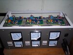
The buck boost system I built originally used a single mosfet (600v 48A 10 milliohhms), I have eight 24v 250W panels all in series, which gives almost 300v open circuit. The dc output voltage is +235v regulated.

Max rated solar panel current about 9 amps. The mosfet sees a peak current of about 40 amps flat out, but the rms current is about 12 amps.
Mosfet dissipation around 15 watts conduction loss plus 2 watts switching loss.
That's probably not bad for 2Kw, giving about 99% efficiency flat out.

A single mosfet does handle the 2KW o/k, but the heatsink is far too small to run at that power for more than a few minutes, even though it only about 17 watts.

So I am in the process of rebuilding it to run two mosfets (5 milliohms) to halve the heat dissipation, and fitting a much larger heatsink, which is probably overkill.

controller1.jpg
 

That's a really nice setup! I like the analogic instruments though I've never used one, as I prefere remote monitoring (and my cases look like black boxes usually).

The mosfet sees a peak current of about 40 amps flat out, but the rms current is about 12 amps.
Mosfet dissipation around 15 watts conduction loss plus 2 watts switching loss.
That's probably not bad for 2Kw, giving about 99% efficiency flat out.

What about the flywheel diode? At 40A rms output current and at least 1V forward voltage, that's a lot of power loss affecting the efficiency.

That's why I only take into consideration a synchronous rectifier at this power level (currents). But the higher voltage rating of the mosfet still remains hence I'll stay with the non-inverting topology.

Moreover, if I'm going to use a positive ground reference for PV panel array I could not (easily) by-pass the charge controller (in case of a failure) to connect the panels right across the battery bank.

I'm talking so much about these automatic manoeuvres because I travel a lot thus my home should be able to help itself when an emergency occurs.
 

I use double pole circuit breakers to isolate my panels. So reversing the polarity to connect direct onto a battery would just require another double pole breaker without needing to worry about ground reference.

The flywheel diode sees the same 12 amps rms, as the mosfet, so you are right about an extra 8 watts loss going into the heatsink, I never really thought about that.
My rectifier is rather oversized 600v, 50A, 50nS.

The peak currents are extremely high, because I am running this in DCM with current mode control. That requires only very simple non critical error amplifier compensation, and it responds extremely quickly to sudden load changes and has very fast current limit. That is important because its driving an inverter directly without having a battery inbetween.

My analog meters are Chinese cheapies, but they have the advantage of not needing to be individually dc powered as digital panel meters would require.

Its pretty easy to get fairly high efficiency at a high voltage, it becomes a bit more difficult to do at 48v.
The flyback inductor needs to be quite large at 2Kw, at 3Kw your magnetics will be quite a monster. That may be another reason to build two 1.5KW controllers.
 
Last edited:
I saw from that picture that your magnetics are pretty small - that's supposed to be my next question!

So you're running it in DCM mode, which is unacceptable for my working currents (50A rms). I have some big sendust toroids and I could stack few of them for the flyback inductor (I'll make some calculation, too).

As time is running out, I'm going to make a test circuit then I'll run some real world measurements.

Btw, I need a similar circuit for my wind turbine so when I'll go into "production mode" I could make few identical modules (1.5 - 2kW rated).
 

Status
Not open for further replies.

Similar threads

Part and Inventory Search

Welcome to EDABoard.com

Sponsor

Back
Top