Continue to Site

Welcome to EDAboard.com

Welcome to our site! EDAboard.com is an international Electronics Discussion Forum focused on EDA software, circuits, schematics, books, theory, papers, asic, pld, 8051, DSP, Network, RF, Analog Design, PCB, Service Manuals... and a whole lot more! To participate you need to register. Registration is free. Click here to register now.

Proteus Simulation Giving Error and stops Simulation.

Status
Not open for further replies.

xpress_embedo

Advanced Member level 4
Joined
Jul 5, 2011
Messages
1,154
Helped
161
Reputation
396
Reaction score
189
Trophy points
1,353
Location
India
Activity points
10,591
Hello! Everyone,

I am trying to make a Dimmer Circuit in Proteus Using Arduino.
In my Simulation, i have three blocks:
1) Arduino Uno
2) Zero Cross Detector Circuit
3) TRIAC Circuit to Control Lamp

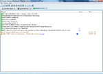
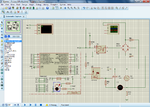
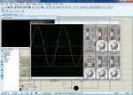
All three works properly when tested individually, but when i combined all the circuits, i am getting the error regarding Timestep too small, Please see images attached below.

Schematic
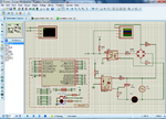
Post.png

Error

Errors.png

Please help me in solving this issue.
I am also attaching the Proteus Design File.

View attachment Dimmer.zip
 

Attachments

  • Dimmer.zip
    108.7 KB · Views: 147

With this type of problem I have found that you should simplify the circuit, say remove U1 and see if that cures the problem, if not remove another component or complete sections until you get it working and then add back components until you get the problem. Changing the resistor type to say digital may help.
 
With this type of problem I have found that you should simplify the circuit, say remove U1 and see if that cures the problem, if not remove another component or complete sections until you get it working and then add back components until you get the problem. Changing the resistor type to say digital may help.

I tried what you say, removing Bridge started my simulation but i am still getting warning Minimum Step and after that Proteus hangs, and is unusable.
I also tried changing resistor from Analog to Digital, and now simulation starts working, but it is of no use, because, after changing all resistors to Digital, i am not getting any signal on Oscilloscope.
So i changed few resistors to Digital which are used on Micro-controller side and rest as Analog, after doing this simulation runs for few second, 2 - 3 seconds displaying all graphs properly and after that, i get the same error.
 

Did you try to change some time related parameters of the Simulation Options panel for transient analysis ? There you can select simulation optimized either to better convergence or better accuracy, or even manually change to another value higher than default.
 
Did you try to change some time related parameters of the Simulation Options panel for transient analysis ? There you can select simulation optimized either to better convergence or better accuracy, or even manually change to another value higher than default.

Thanks for your reply, and i had tried both (convergence and accuracy) these settings before posting here and none of them works for me.
Strange thing is that, all of these modules are working dependently.
 

Hi,

there is the left side of the schematic referring to GND (Symbol)
and there is the right side (mains) of the schematic. It has no connection to GND. Some simulators have problems with this.
--> a very high ohmic resistor (100M) between both sides could help to run the simulation.

In either way I see a possible problem with the scope. I assume it references it´s signals to GND, which is impossible with Input "A" = mains side.

Klaus

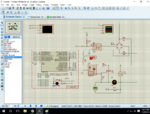
Thank You, i connected a 100MOhm Resistor as shown in the image below of Analog Type.
And After that R2, R8, R9, R10 is Analog while R3, R1 is Digital.

Currently the simulation is working, let's see if i get error after writing the program or not.

Thanks for your help.

Simulation Started.png

Updated.png
 

I started writing the code for Arduino, i tested Zero Cross signal and i am able to detect zero cross signal successfully using Arduino's External Interrupt and it is working properly.

Now its time to turn on the triac, i get Zero Cross Signal every 10ms and after 5ms of receiving zero cross, i turn on the triac driving GPIO pin of Arduino, and in zero cross interrupt i turn this pin off and similarly after 5 ms it will get turn on again.
My intention in doing so is to operate lamp at 50% power by cutting half phase.

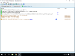
But after doing so i am getting the same error again.
I disconnect TRIAC driving pin from Arduino, and used a Logic State to turn on-off the TRIAC, and it works fine, until i increase my Logic State On-Off speed.

Schematic.png

Error.png

Can anyone please provide comments to resolve this issue.
I am attaching my Proteus Design File here.

View attachment Dimmer.zip
 

Status
Not open for further replies.

Part and Inventory Search

Welcome to EDABoard.com

Sponsor

Back
Top