Continue to Site

Welcome to EDAboard.com

Welcome to our site! EDAboard.com is an international Electronics Discussion Forum focused on EDA software, circuits, schematics, books, theory, papers, asic, pld, 8051, DSP, Network, RF, Analog Design, PCB, Service Manuals... and a whole lot more! To participate you need to register. Registration is free. Click here to register now.

Problem with using Arduino to detect weight from a Load Cell and INA126P IN AMP

Status
Not open for further replies.

rossp3904

Newbie level 2
Joined
Nov 17, 2016
Messages
2
Helped
0
Reputation
0
Reaction score
0
Trophy points
1
Activity points
26
I am trying so set up a 4 wire load cell to measure weight. I have it connected to a INA126P in amp and that is connected to the Arduino Uno. I am not detecting any response when I apply weight to the load cell, and I don't know what is going on. If anyone can help, I would greatly appreciate the advice.

This is the load cell that I am using: https://www.phidgets.com/products.php?category=34&product_id=3136_0

Here are the connections I have:

Load Cell
Red (E+) - 5V​
Black (E-) - GND​
Green (S+) - V+ in (INA126 Pin #3)​
White (S-) - V- in (INA126 Pin #2)​

INA126P
Pin 1 & 8 - Gain Resistor (Tried none, 80, and 1k)​
Pin 2 (V- In) - White Load Cell Wire​
Pin 3 (V+ Out) - Green Load Cell Wire​
Pin 4 (V-) - GND​
Pin 5 (Ref) - GND​
Pin 6 (Vo) - Arduino Pin A0​
Pin 7 (V+) - 5V​


Arduino Code:

void setup() {
Serial.begin(9600);
}

void loop() {
Serial.println(A0);
delay(200);
}
 

Hi,

There is no error description, no description how you tested it, no information what you expect and no description what you see.
Therefore it is impossible for us to give detailed answers.

A schematic is way more descriptive than your description.

A load cell output can be positive and negative. But your amplifier can process positvie input only.
If now the load cell offset voltage is negative it will output zero voltage.

Klaus
 

Sorry, I am a relative EE newbie and absolute EDA Board newbie.

So, the code runs but it outputs "14" continuously. I applied a varying amount of weight to the Load cell and received no change. I swapped out the INA126P, the load cell, the gain resistor, reversed the polarity of the load cell, and tested the arduino. I also changed the reference voltage from ground to 2.5V using a voltage divider.

I am expecting the value to vary when you apply weight to the load cell. I know it is a 10-bit ADC so I am not expecting much precision, but I am getting no change at all.

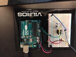
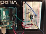
I am attaching a schematic and images of the circuitry.

Thanks for all your help!


https://obrazki.elektroda.pl/8570926500_1479487573.jpg
https://obrazki.elektroda.pl/9593363700_1479487574.jpg
https://obrazki.elektroda.pl/6278614500_1479487576.jpg


IMG_8864.jpgIMG_8863.jpgINA126P with Load Cell.JPG
 

Hi,

the resistors for the voltage divider are really 27 Ohms each? then the become hot. I´d use 100 Ohms each. Datasheet says this is degrading common mode rejection. I dot see a problem with your circuit.

I don´t see a mistake.

Please measure the voltages: wrt GND. directely with the voltmeter tip on the INA leg.
* VCC
* IN+
* IN-
* Output

Klaus
 

Status
Not open for further replies.

Part and Inventory Search

Welcome to EDABoard.com

Sponsor

Back
Top