hafrse
Full Member level 3
Hello,
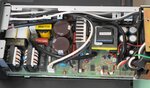
I have newly purchased a used Icom PS-125 12V 25A power supply and found that it gives a mechanical buzz sound at about 100 Hz (50 hz mains freq.) under load. The buzz gets higher if the load is higher. On about 1-2A the buzz i barely heard.
Do I suspect the large filter 1200uf electrolytes located after the full wave rectifier (C9 and C10) ? any thing else can cause this buzz ?
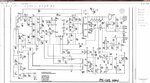
Attached the schematics.
Thanks
- - - Updated - - -
Brief operational description taken from the manual:
A. Primary DC supply
1. AC input voltage is applied through the AC switch, to input fuse F-1 and filters IF1, IF2, and
associated capacitors C1-5, C24 & C25, through R-2 to the primary rectifier array D-1. Triac Q-1
that is connected across R-2 conducts once the switching supply starts, thus limiting the voltage
drop across R-2. A movable jumper from D-1 to the junction of C-9 & C-10 configures the
primary supply for 110-volt operation as a voltage doubler. For 220-volt operation, this jumper
is not connected. The +310 volt DC output voltage of D1 is connected through L2, & D2 to series
connected electrolytic capacitors C-9 & C-10 which filter the DC output voltage of D-1.
B. Switching supply
1. The output of the primary 310V DC supply is now applied to series connected power FETs Q4 &
Q5 and the primary of high frequency transformer T-1. Switch mode controller IC, HIC-1, drives
the gates of Q4 & Q5. Upon initial power application, Q4 or Q5 will conduct first, thus causing
an ac output voltage on all secondary windings of T-1. The voltage of T-1 pins 7 & 8 is rectified
by D-8, regulated by D-9 & Q-6 and applied to HIC-1 pin 12 (vcc) to operate HIC-1. The voltage
from T-1 pins 9 &10 is rectified by D23, & filtered by C40 to supply voltage for all IC’s and
transistors except HIC-1. HIC-1 now begins operating and alternately drives Q4 & Q5 at a high
AC frequency.
C. Secondary DC supply
1. T-1 secondary windings pins 12 & 13, 16 & 17, 14 & 15, 10 &11 and fast recovery diodes D 21 &
D22, along with electrolytic capacitors C31,32,33.34.& 35 form the 25 amp 13.8 volt DC output
supply. The output is applied to the output terminals through L-12 & L-13.
2. The 13.8 Volt DC output is sensed via R-58 to the base of Q-11, the collector of which drives
opto- isolator PC-1. Adjustment of VR-11adjusts the base voltage of Q-11 thus establishing via
HIC-1, the power supply DC output voltage.
3. IC-11 pins 1, 2, & 3 sense the voltage drop across R-31 & R-32 via VR-12 and R-44, to establish
via the adjustment of VR-12, the maximum output current limit.
4. Zener diode D-26, Q13, R-48, R-49, PC-2 and associated components detect an over voltage
condition of the 13.8 volt supply output.
5. IC-11, pins 5,6, & 7, Q-14 & associated components sense temperature rise inside the supply via
Thermistor R54 which touches power transformer T-1 and turns on the fan as appropriate
I have newly purchased a used Icom PS-125 12V 25A power supply and found that it gives a mechanical buzz sound at about 100 Hz (50 hz mains freq.) under load. The buzz gets higher if the load is higher. On about 1-2A the buzz i barely heard.
Do I suspect the large filter 1200uf electrolytes located after the full wave rectifier (C9 and C10) ? any thing else can cause this buzz ?
Attached the schematics.
Thanks
- - - Updated - - -
Added the schemtics
Brief operational description taken from the manual:
A. Primary DC supply
1. AC input voltage is applied through the AC switch, to input fuse F-1 and filters IF1, IF2, and
associated capacitors C1-5, C24 & C25, through R-2 to the primary rectifier array D-1. Triac Q-1
that is connected across R-2 conducts once the switching supply starts, thus limiting the voltage
drop across R-2. A movable jumper from D-1 to the junction of C-9 & C-10 configures the
primary supply for 110-volt operation as a voltage doubler. For 220-volt operation, this jumper
is not connected. The +310 volt DC output voltage of D1 is connected through L2, & D2 to series
connected electrolytic capacitors C-9 & C-10 which filter the DC output voltage of D-1.
B. Switching supply
1. The output of the primary 310V DC supply is now applied to series connected power FETs Q4 &
Q5 and the primary of high frequency transformer T-1. Switch mode controller IC, HIC-1, drives
the gates of Q4 & Q5. Upon initial power application, Q4 or Q5 will conduct first, thus causing
an ac output voltage on all secondary windings of T-1. The voltage of T-1 pins 7 & 8 is rectified
by D-8, regulated by D-9 & Q-6 and applied to HIC-1 pin 12 (vcc) to operate HIC-1. The voltage
from T-1 pins 9 &10 is rectified by D23, & filtered by C40 to supply voltage for all IC’s and
transistors except HIC-1. HIC-1 now begins operating and alternately drives Q4 & Q5 at a high
AC frequency.
C. Secondary DC supply
1. T-1 secondary windings pins 12 & 13, 16 & 17, 14 & 15, 10 &11 and fast recovery diodes D 21 &
D22, along with electrolytic capacitors C31,32,33.34.& 35 form the 25 amp 13.8 volt DC output
supply. The output is applied to the output terminals through L-12 & L-13.
2. The 13.8 Volt DC output is sensed via R-58 to the base of Q-11, the collector of which drives
opto- isolator PC-1. Adjustment of VR-11adjusts the base voltage of Q-11 thus establishing via
HIC-1, the power supply DC output voltage.
3. IC-11 pins 1, 2, & 3 sense the voltage drop across R-31 & R-32 via VR-12 and R-44, to establish
via the adjustment of VR-12, the maximum output current limit.
4. Zener diode D-26, Q13, R-48, R-49, PC-2 and associated components detect an over voltage
condition of the 13.8 volt supply output.
5. IC-11, pins 5,6, & 7, Q-14 & associated components sense temperature rise inside the supply via
Thermistor R54 which touches power transformer T-1 and turns on the fan as appropriate
Attachments
Last edited:
")