Continue to Site

Welcome to EDAboard.com

Welcome to our site! EDAboard.com is an international Electronics Discussion Forum focused on EDA software, circuits, schematics, books, theory, papers, asic, pld, 8051, DSP, Network, RF, Analog Design, PCB, Service Manuals... and a whole lot more! To participate you need to register. Registration is free. Click here to register now.

[PIC] How do i perform multiple tasks in mikrobasic for PIC12 series?

Status
Not open for further replies.

SparkyChem

Member level 3
Joined
Apr 22, 2010
Messages
57
Helped
0
Reputation
0
Reaction score
0
Trophy points
1,286
Location
Lima, Peru
Activity points
2,084
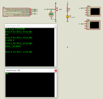
I am trying to make a simple project in mikrobasic using PIC12F1840. This includes to toggle on and off a led in Port RA0 at a frequency of 1Hz (led blinking), at the same time recording ADC values from a potentiometer from 0 to 5v max in Port RA1 at 10 bits and simultaneously sending those values to the computer via RS232 to be read through hyperterminal.

However before showing the results the pic would ask the user if the desired value would be between 0 to 1023 or 0 to 4.999 v, in other words asking the user which unit desires. I understand that the way to achieve this is using timer interrupts however i don't know how to use these in mikrobasic, mind anyone sharing a code or an example on how do i solve this problem?. Thanks.
 

Use mikroE Timer Calculator tool available at libstock.com

Select PIC16F, 4 MHz, Timer1, 500 ms and generate the code. Copy Paste it into your mikroBasic PRO PIC Project. Write ADC and UART code.
 

Use mikroE Timer Calculator tool available at libstock.com

Select PIC16F, 4 MHz, Timer1, 500 ms and generate the code. Copy Paste it into your mikroBasic PRO PIC Project. Write ADC and UART code.

Shouldn't that be PIC12F in my case??. Either way, why 500ms?. Can you show me an example of how do i use it with the ADC and UART codes you mentioned?. I am still learning.
 

Hi

Here is the project. I don't use mikroBasic and hence I have posted mikroC code. You can easily port it to mikroBasic. Proteus file included. See attached video.

Either way, why 500ms?

With 4 MHz Oscillator you can create max 523.x or something near that delay. I choose 500 ms because with a counter we can have multiples of 500 ms as you need 1 sec delay for LED.


Code C - [expand]
1
2
3
4
5
6
7
8
9
10
11
12
13
14
15
16
17
18
19
20
21
22
23
24
25
26
27
28
29
30
31
32
33
34
35
36
37
38
39
40
41
42
43
44
45
46
47
48
49
50
51
52
53
54
55
56
57
58
59
60
61
62
63
64
65
66
67
68
69
70
71
72
73
74
75
76
77
78
79
80
81
82
83
84
85
86
87
88
89
90
91
92
93
sbit LED at LATA4_bit;
 
const code char msg1[] = "ADC Using PIC12F1840\r\n";
const code char msg2[] = "--------------------\r\n";
 
char msg[50], counter = 0;
unsigned int raw_adc_value = 0, previous_raw_adc_value = 0;
 
//Timer1
//Prescaler 1:8; TMR1 Preload = 3036; Actual Interrupt Time : 500 ms
//Place/Copy this part in declaration section
void InitTimer1() {
    T1CON = 0x31;
    TMR1IF_bit = 0;
    TMR1H = 0x0B;
    TMR1L = 0xDC;
    TMR1IE_bit = 1;
    INTCON = 0xC0;
}
 
void Interrupt() {
    if(TMR1IF_bit) {
      TMR1IF_bit = 0;
      TMR1H = 0x0B;
      TMR1L = 0xDC;
      //Enter your code here
      if(++counter == 2) {
          LED = ~LED;
          counter = 0;
      }
    }
}
 
// copy const to ram string
char *CopyConst2Ram(char *dest, const char *src) {
    char *d;
    d = dest;
 
    for(;*dest++ = *src++;)asm clrwdt;
 
    return d;
}
 
void main() {
 
    asm clrwdt
    OSCCON = 0b01101011;
    OSCSTAT = 0x91;
    OSCTUNE = 0x00;
    OPTION_REG = 0x8F;
    CM1CON0 = 0x00;
    ADCON1 = 0b11010000;
    ANSELA = 0x04;
    TRISA = 0x04;
    PORTA = 0x00;
    LATA = 0x00;
    
    asm clrwdt
    UART1_Init(9600);
    Delay_ms(200);
    asm clrwdt
    
    UART1_Write_Text(CopyConst2Ram(msg, msg1));
    asm clrwdt
    UART1_Write_Text(CopyConst2Ram(msg, msg2));
    asm clrwdt
 
    InitTimer1();
    
    while(1) {
    
           asm clrwdt
           
           raw_adc_value = ADC_Read(2);
           Delay_ms(20);
           
           if(previous_raw_adc_value != raw_adc_value) {
                IntToStr(raw_adc_value, msg);
                asm clrwdt
                Ltrim(msg);
                asm clrwdt
                Rtrim(msg);
                asm clrwdt
                strcat(msg, "\r\n");
                asm clrwdt
                
                UART1_Write_Text(msg);
                asm clrwdt
                
                previous_raw_adc_value = raw_adc_value;
           }
    }
}


- - - Updated - - -

Edit:

Hi

Here is the mikroBasic Code. I had to read the help file to make the mikroBasic code.


Code - [expand]
1
2
3
4
5
6
7
8
9
10
11
12
13
14
15
16
17
18
19
20
21
22
23
24
25
26
27
28
29
30
31
32
33
34
35
36
37
38
39
40
41
42
43
44
45
46
47
48
49
50
51
52
53
54
55
56
57
58
59
60
61
62
63
64
65
66
67
68
69
70
71
72
73
74
75
76
77
78
79
80
81
82
83
84
85
86
87
88
89
90
91
92
93
94
95
96
97
98
99
100
101
program Multitasking_with_PIC12F1840
 
' Declarations section
 
dim LED as sbit at LATA.4
 
dim msg1 as string[22]
dim msg2 as string[22]
 
dim msg as string[50]
dim counter as byte
dim raw_adc_value as word
dim previous_raw_adc_value as word
 
'Timer1
'Prescaler 1:8; TMR1 Preload = 3036; Actual Interrupt Time : 500 ms
'Place/Copy this part in declaration section
sub procedure InitTimer1()
    asm clrwdt end asm
    T1CON = 0x31
    TMR1IF_bit = 0
    TMR1H = 0x0B
    TMR1L = 0xDC
    TMR1IE_bit = 1
    INTCON = 0xC0
    asm clrwdt end asm
end sub
 
sub procedure Interrupt()
    if(TMR1IF_bit) then
      TMR1IF_bit = 0
      TMR1H = 0x0B
      TMR1L = 0xDC
      'Enter your code here
      counter = counter + 1
 
      if counter = 2 then
          LED = not LED
          counter = 0
      end if
    end if
end sub
 
main:
'   Main program
    asm clrwdt end asm
    
    msg1 = "ADC Using PIC12F1840"
    msg2 = "--------------------"
    
    OSCCON = %01101011
    OSCSTAT = $91
    OSCTUNE = $00
    OPTION_REG = $8F
    CM1CON0 = $00
    ADCON1 = %11010000
    ANSELA = $04
    TRISA = $04
    PORTA = $00
    LATA = $00
 
    asm clrwdt end asm
    UART1_Init(9600)
    Delay_ms(200)
    asm clrwdt end asm
 
    UART1_Write_Text(msg1)
    UART1_Write($0D)
    UART1_Write($0A)
    asm clrwdt end asm
    UART1_Write_Text(msg2)
    UART1_Write($0D)
    UART1_Write($0A)
    asm clrwdt end asm
 
    InitTimer1()
    
    while(TRUE)
       asm clrwdt end asm
 
       raw_adc_value = ADC_Read(2)
       Delay_ms(20)
 
       if previous_raw_adc_value <> raw_adc_value then
            IntToStr(raw_adc_value, msg)
            asm clrwdt end asm
            Ltrim(msg)
            asm clrwdt end asm
            Rtrim(msg)
            asm clrwdt end asm
            asm clrwdt end asm
 
            UART1_Write_Text(msg)
            UART1_Write($0D)
            UART1_Write($0A)
            asm clrwdt end asm
 
            previous_raw_adc_value = raw_adc_value
       end if
    wend
end.


Attachments

  • Multitasking with PIC12F1840.rar
    68.3 KB · Views: 117
  • Multitasking with PIC12F1840.rar
    97.3 KB · Views: 106
Last edited:
A classic way of doing multiple tasks (semi-)simultaneously is to put each into a function that is called within the main loop of the program. Within each function you create a state machine so that you can check if everything is ready to move to the next state an execute the required operation.
If any task must be performed on a regular basis, then (as suggested above) use a timer that will advance the state machine at the appropriate time. (If there are multiple timed tasks then set the timer so that each task interval is an integer multiple of the timer and trigger the state transitions accordingly. This is an extension of the technique that Okada showed with the 500mSec timer for a 1s interval.)
You can also use interrupts to advance the state of a particular operation if that is appropriate (e.g. responding to a received character).
I have used this technique many times and it works well. It also lets you think about the way each operation works (more or less) in isolation from all of the others which stops bugs spreading into areas that have already been found to work. It also lets you build up the functionality gradually, one operation at a time.
Susan
 
Here is the new code. Moved the strings to ROM.


Code - [expand]
1
2
3
4
5
6
7
8
9
10
11
12
13
14
15
16
17
18
19
20
21
22
23
24
25
26
27
28
29
30
31
32
33
34
35
36
37
38
39
40
41
42
43
44
45
46
47
48
49
50
51
52
53
54
55
56
57
58
59
60
61
62
63
64
65
66
67
68
69
70
71
72
73
74
75
76
77
78
79
80
81
82
83
84
85
86
87
88
89
90
91
92
93
94
95
96
97
98
99
100
101
102
103
104
105
106
107
108
109
program Multitasking_with_PIC12F1840
 
' Declarations section
 
dim LED as sbit at LATA.4
 
dim const msg1 as string[22] = "ADC Using PIC12F1840"
dim const msg2 as string[22] = "--------------------"
 
dim msg as string[50]
dim counter as byte
dim raw_adc_value as word
dim previous_raw_adc_value as word
 
'Timer1
'Prescaler 1:8; TMR1 Preload = 3036; Actual Interrupt Time : 500 ms
'Place/Copy this part in declaration section
sub procedure InitTimer1()
    asm clrwdt end asm
    T1CON = 0x31
    TMR1IF_bit = 0
    TMR1H = 0x0B
    TMR1L = 0xDC
    TMR1IE_bit = 1
    INTCON = 0xC0
    asm clrwdt end asm
end sub
 
sub procedure Interrupt()
    if(TMR1IF_bit) then
      TMR1IF_bit = 0
      TMR1H = 0x0B
      TMR1L = 0xDC
      'Enter your code here
      counter = counter + 1
 
      if counter = 2 then
          LED = not LED
          counter = 0
      end if
    end if
end sub
 
sub function CopyConst2Ram(dim dest as ^char, dim src as ^const char) as ^char
    result = dest
 
    while(true)
      dest^ = src^
      if dest^ = 0 then exit end if
      inc(dest)
      inc(src)
    wend
 
end sub
 
main:
'   Main program
    asm clrwdt end asm
    
    OSCCON = %01101011
    OSCSTAT = $91
    OSCTUNE = $00
    OPTION_REG = $8F
    CM1CON0 = $00
    ADCON1 = %11010000
    ANSELA = $04
    TRISA = $04
    PORTA = $00
    LATA = $00
 
    asm clrwdt end asm
    UART1_Init(9600)
    Delay_ms(200)
    asm clrwdt end asm
 
    UART1_Write_Text(CopyConst2Ram(@msg, @msg1))
    UART1_Write($0D)
    UART1_Write($0A)
    asm clrwdt end asm
    UART1_Write_Text(CopyConst2Ram(@msg, @msg2))
    UART1_Write($0D)
    UART1_Write($0A)
    asm clrwdt end asm
 
    InitTimer1()
    
    while(TRUE)
       asm clrwdt end asm
 
       raw_adc_value = ADC_Read(2)
       Delay_ms(20)
 
       if previous_raw_adc_value <> raw_adc_value then
            IntToStr(raw_adc_value, msg)
            asm clrwdt end asm
            Ltrim(msg)
            asm clrwdt end asm
            Rtrim(msg)
            asm clrwdt end asm
 
            UART1_Write_Text(msg)
            UART1_Write($0D)
            UART1_Write($0A)
            asm clrwdt end asm
 
            previous_raw_adc_value = raw_adc_value
       end if
    wend
end.


Hi. Thanks for your response. I tried to run the simulation in my computer but the LED did not blink with the code in mikrobasic. The mikroC code it seems correct but the other one is not right. I dont know the reason.

It must be noted that you're using 9600 baud rate, 8 data bits, no parity, 1 stop bit and RT/TX normal polarity. However there is missing one thing with the RS232 question from above and that is an option that should appear asking the user to type or enter if the result is Volts or just raw ADC conversion.

I mean in the title during serial communication say

ADC Using PIC12F1840
--------------------

511

but how do i make it like this way?.

ADC Using PIC12F1840
--------------------

Enter desired unit V for volts, R for raw:

(any other caracter will return the message 'error' and would ask try again)

Now if the user desires to end the program would press S.

Shouldn't this would require to use 'select case' statement in the main loop or after?.

By the way, this part in the code i dont get it,
Code:
asm clrwdt end asm

Why is it using asm within mikrobasic?. Or is this generated by the tool you were referring earlier?.
 

Don't get too carried away with the code to clear the WDT (the asm clrwdt thing) - in this situation it is only confusing the rest of the code.
Most PIC devices have a 'watch dog timer' that causes a reset of the device is the timer is not reset every so often. This can be very useful if some strange condition causes an embedded device to 'lock up'; by performing a reset it can again perform the required tasks.
However it is one of the things that should be added to the code right at the end of the development cycle, just before the final testing before release. If you are not careful it can add more problems than it is supposed to solve.
Also, you need to be very careful where you do 'pat the dog' (as it is sometimes called) and it should be done only from the main loop (which should always be returned to in normal operation. If you put in too many of these instructions, you can end up patting the dog in the middle of your problem and so the whole thing becomes totally ineffective.
My suggestion for now is to turn off the WDT (in the config settings and possibly also in the initialisation part of your code) and remove all of these extraneous 'clrwdt' references.
Susan
 
Here is the modified project.

Regarding the sam code it is known as inline asm code. I have enabled the Watch Dog Timer to make sure the device runs all the time and as such to clear WDt I have used asm code.


Code - [expand]
1
2
3
4
5
6
7
8
9
10
11
12
13
14
15
16
17
18
19
20
21
22
23
24
25
26
27
28
29
30
31
32
33
34
35
36
37
38
39
40
41
42
43
44
45
46
47
48
49
50
51
52
53
54
55
56
57
58
59
60
61
62
63
64
65
66
67
68
69
70
71
72
73
74
75
76
77
78
79
80
81
82
83
84
85
86
87
88
89
90
91
92
93
94
95
96
97
98
99
100
101
102
103
104
105
106
107
108
109
110
111
112
113
114
115
116
117
118
119
120
121
122
123
124
125
126
127
128
129
130
131
132
133
134
135
136
137
138
139
140
141
142
143
144
145
146
147
148
149
150
151
152
153
154
155
156
157
158
159
160
161
162
163
164
165
166
167
program Multitasking_with_PIC12F1840
 
' Declarations section
 
dim LED as sbit at LATA.4
 
dim const msg1 as string[20] = "ADC Using PIC12F1840"
dim const msg2 as string[20] = "--------------------"
dim const msg3 as string[29] = "Enter V for Volts, R for Raw"
dim const msg4 as string[29] = "----------------------------"
dim const msg5 as string[17] = "Error, Try Again"
dim const msg6 as string[17] = "----------------"
 
dim msg as string[50]
dim uart_rd as byte
dim myFlags as byte
dim counter as byte
dim raw_adc_value as word
dim adc_value as double
 
dim data_received_flag as sbit at myFlags.0
 
'Timer1
'Prescaler 1:8; TMR1 Preload = 3036; Actual Interrupt Time : 500 ms
'Place/Copy this part in declaration section
sub procedure InitTimer1()
    asm clrwdt end asm
    T1CON = 0x31
    TMR1IF_bit = 0
    TMR1H = 0x0B
    TMR1L = 0xDC
    TMR1IE_bit = 1
    INTCON = intcon or 0xC0
    asm clrwdt end asm
end sub
 
sub procedure Interrupt()
    if((TMR1IE_bit) and (TMR1IF_bit)) then
      TMR1IF_bit = 0
      TMR1H = 0x0B
      TMR1L = 0xDC
      'Enter your code here
      counter = counter + 1
 
      if counter = 2 then
          LED = not LED
          counter = 0
      end if
    end if
    
    if((RCIE_bit) and (RCIF_bit)) then
         if OERR_bit then
             OERR_bit = 0
             CREN_bit = 0
             CREN_bit = 1
         end if
         
         uart_rd = UART1_Read()
         
         RCIF_bit = 0
    end if
end sub
 
sub function CopyConst2Ram(dim dest as ^char, dim src as ^const char) as ^char
    result = dest
 
    while(true)
      dest^ = src^
      if dest^ = 0 then exit end if
      inc(dest)
      inc(src)
    wend
 
end sub
 
sub procedure NewLine()
    UART1_Write($0D)
    UART1_Write($0A)
end sub
 
sub procedure Trim_Data()
    Ltrim(msg)
    asm clrwdt end asm
    Rtrim(msg)
    asm clrwdt end asm
end sub
 
main:
'   Main program
    asm clrwdt end asm
    
    OSCCON = %01101011
    OSCSTAT = $91
    OSCTUNE = $00
    OPTION_REG = $8F
    CM1CON0 = $00
    ADCON1 = %11010000
    ANSELA = $04
    TRISA = %000110
    PORTA = $00
    LATA = $00
 
    asm clrwdt end asm
    UART1_Init(9600)
    Delay_ms(200)
    asm clrwdt end asm
 
    UART1_Write_Text(CopyConst2Ram(@msg, @msg1))
    NewLine()
    asm clrwdt end asm
    UART1_Write_Text(CopyConst2Ram(@msg, @msg2))
    NewLine()
    asm clrwdt end asm
 
    RCIF_bit = 0
    RCIE_bit = 1
 
    UART1_Write_Text(CopyConst2Ram(@msg, @msg3))
    NewLine()
    UART1_Write_Text(CopyConst2Ram(@msg, @msg4))
    NewLine()
    
    InitTimer1()
    
    while(TRUE)
       asm clrwdt end asm
 
       raw_adc_value = ADC_Read(2)
       Delay_ms(20)
 
       if uart_rd then
            select case uart_rd
                case "V"
                     adc_value = raw_adc_value * 5.0 / 1023.0
                     FloatToStr(adc_value, msg)
                     asm clrwdt end asm
                     Trim_Data()
                     strcat(msg, " V")
                     UART1_Write_Text(msg)
                case "R"
                     IntToStr(raw_adc_value, msg)
                     asm clrwdt end asm
                     Trim_Data()
                     UART1_Write_Text(msg)
                case "S"
                     asm reset end asm
                case else
                     UART1_Write_Text(CopyConst2Ram(@msg, @msg5))
                     NewLine()
                     UART1_Write_Text(CopyConst2Ram(@msg, @msg6))
                     NewLine()
            end select
 
            NewLine()
            NewLine()
            asm clrwdt end asm
            asm clrwdt end asm
            UART1_Write_Text(CopyConst2Ram(@msg, @msg3))
            NewLine()
            UART1_Write_Text(CopyConst2Ram(@msg, @msg4))
            NewLine()
            asm clrwdt end asm
            
            uart_rd = 0
       end if
    wend
end.


Attachments

  • Multitasking with PIC12F1840.rar
    29.2 KB · Views: 99
  • simulation result.png
    simulation result.png
    29.5 KB · Views: 141
Last edited:
Okada - see my comments about the inappropriate use of the WDT in your code. For example, you have consecutive liners of code where you clear the WDT - that is just a waste of processor time.
Also you clear the WDT multiple times in the initialisation code - unless you expect that to take muck longer than the WDT timeout (which could well indicate a design fault) then you can leave all of those out of the code. You should clear the WDT once at (say) the top of the main loop but nowhere else otherwise it is probably just going to mask any faults that may be in the coding or hardware design.
Susan
 
@Aussie Susan

Ok. I will fix it after checking how much time each instruction takes to execute.

- - - Updated - - -

Edit:

Here is the fixed code.

https://www.hobbyprojects.com/pic_tutorials/tutorial13.html


Code - [expand]
1
2
3
4
5
6
7
8
9
10
11
12
13
14
15
16
17
18
19
20
21
22
23
24
25
26
27
28
29
30
31
32
33
34
35
36
37
38
39
40
41
42
43
44
45
46
47
48
49
50
51
52
53
54
55
56
57
58
59
60
61
62
63
64
65
66
67
68
69
70
71
72
73
74
75
76
77
78
79
80
81
82
83
84
85
86
87
88
89
90
91
92
93
94
95
96
97
98
99
100
101
102
103
104
105
106
107
108
109
110
111
112
113
114
115
116
117
118
119
120
121
122
123
124
125
126
127
128
129
130
131
132
133
134
135
136
137
138
139
140
141
142
143
144
145
146
147
148
149
150
151
152
153
154
155
156
program Multitasking_with_PIC12F1840
 
' Declarations section
 
dim LED as sbit at LATA.4
 
dim const msg1 as string[20] = "ADC Using PIC12F1840"
dim const msg2 as string[20] = "--------------------"
dim const msg3 as string[29] = "Enter V for Volts, R for Raw"
dim const msg4 as string[29] = "----------------------------"
dim const msg5 as string[17] = "Error, Try Again"
dim const msg6 as string[17] = "----------------"
 
dim msg as string[50]
dim uart_rd as byte
dim myFlags as byte
dim counter as byte
dim raw_adc_value as word
dim adc_value as double
 
dim data_received_flag as sbit at myFlags.0
 
'Timer1
'Prescaler 1:8; TMR1 Preload = 3036; Actual Interrupt Time : 500 ms
'Place/Copy this part in declaration section
sub procedure InitTimer1()
    asm clrwdt end asm
    T1CON = 0x31
    TMR1IF_bit = 0
    TMR1H = 0x0B
    TMR1L = 0xDC
    TMR1IE_bit = 1
    INTCON = intcon or 0xC0
end sub
 
sub procedure Interrupt()
    if((TMR1IE_bit) and (TMR1IF_bit)) then
      TMR1IF_bit = 0
      TMR1H = 0x0B
      TMR1L = 0xDC
      'Enter your code here
      counter = counter + 1
 
      if counter = 2 then
          LED = not LED
          counter = 0
      end if
    end if
    
    if((RCIE_bit) and (RCIF_bit)) then
         if OERR_bit then
             OERR_bit = 0
             CREN_bit = 0
             CREN_bit = 1
         end if
         
         uart_rd = UART1_Read()
         
         RCIF_bit = 0
    end if
end sub
 
sub function CopyConst2Ram(dim dest as ^char, dim src as ^const char) as ^char
    result = dest
 
    while(true)
      dest^ = src^
      if dest^ = 0 then exit end if
      inc(dest)
      inc(src)
    wend
 
end sub
 
sub procedure NewLine()
    UART1_Write($0D)
    UART1_Write($0A)
end sub
 
sub procedure Trim_Data()
    Ltrim(msg)
    Rtrim(msg)
end sub
 
main:
'   Main program
    asm clrwdt end asm
    
    OSCCON = %01101011
    OSCSTAT = $91
    OSCTUNE = $00
    OPTION_REG = $8F
    CM1CON0 = $00
    ADCON1 = %11010000
    ANSELA = $04
    TRISA = %000110
    PORTA = $00
    LATA = $00
 
    UART1_Init(9600)
    Delay_ms(200)
 
    UART1_Write_Text(CopyConst2Ram(@msg, @msg1))
    NewLine()
    UART1_Write_Text(CopyConst2Ram(@msg, @msg2))
    NewLine()
 
    RCIF_bit = 0
    RCIE_bit = 1
 
    UART1_Write_Text(CopyConst2Ram(@msg, @msg3))
    NewLine()
    UART1_Write_Text(CopyConst2Ram(@msg, @msg4))
    NewLine()
    
    InitTimer1()
    
    while(TRUE)
    
       asm clrwdt end asm
 
       raw_adc_value = ADC_Read(2)
       Delay_ms(20)
 
       if uart_rd then
            select case uart_rd
                case "V"
                     adc_value = raw_adc_value * 5.0 / 1023.0
                     FloatToStr(adc_value, msg)
                     Trim_Data()
                     strcat(msg, " V")
                     UART1_Write_Text(msg)
                case "R"
                     IntToStr(raw_adc_value, msg)
                     Trim_Data()
                     UART1_Write_Text(msg)
                case "S"
 
                case else
                     UART1_Write_Text(CopyConst2Ram(@msg, @msg5))
                     NewLine()
                     UART1_Write_Text(CopyConst2Ram(@msg, @msg6))
                     NewLine()
            end select
 
            NewLine()
            NewLine()
            UART1_Write_Text(CopyConst2Ram(@msg, @msg3))
            NewLine()
            UART1_Write_Text(CopyConst2Ram(@msg, @msg4))
            NewLine()
            
            uart_rd = 0
       end if
    wend
end.


Attachments

  • mikroBasic PRO PIC.rar
    13.5 KB · Views: 106
Don't get too carried away with the code to clear the WDT (the asm clrwdt thing) - in this situation it is only confusing the rest of the code.
Most PIC devices have a 'watch dog timer' that causes a reset of the device is the timer is not reset every so often. This can be very useful if some strange condition causes an embedded device to 'lock up'; by performing a reset it can again perform the required tasks.
However it is one of the things that should be added to the code right at the end of the development cycle, just before the final testing before release. If you are not careful it can add more problems than it is supposed to solve.
Also, you need to be very careful where you do 'pat the dog' (as it is sometimes called) and it should be done only from the main loop (which should always be returned to in normal operation. If you put in too many of these instructions, you can end up patting the dog in the middle of your problem and so the whole thing becomes totally ineffective.
My suggestion for now is to turn off the WDT (in the config settings and possibly also in the initialisation part of your code) and remove all of these extraneous 'clrwdt' references.
Susan

So in short does it mean that if you add too many interrupts this causes the PIC to reset itself because of the WDT thing?. But when you need to perform too many tasks what other ways are to resort?. State machine, RTOs? i have read some about these but i think by using interrupts is more easier or user friendly. Can you explain this a bit more please?.

@Aussie Susan

Ok. I will fix it after checking how much time each instruction takes to execute.

- - - Updated - - -

Edit:

Here is the fixed code.

https://www.hobbyprojects.com/pic_tutorials/tutorial13.html


Code - [expand]
1
2
3
4
5
6
7
8
9
10
11
12
13
14
15
16
17
18
19
20
21
22
23
24
25
26
27
28
29
30
31
32
33
34
35
36
37
38
39
40
41
42
43
44
45
46
47
48
49
50
51
52
53
54
55
56
57
58
59
60
61
62
63
64
65
66
67
68
69
70
71
72
73
74
75
76
77
78
79
80
81
82
83
84
85
86
87
88
89
90
91
92
93
94
95
96
97
98
99
100
101
102
103
104
105
106
107
108
109
110
111
112
113
114
115
116
117
118
119
120
121
122
123
124
125
126
127
128
129
130
131
132
133
134
135
136
137
138
139
140
141
142
143
144
145
146
147
148
149
150
151
152
153
154
155
156
program Multitasking_with_PIC12F1840
 
' Declarations section
 
dim LED as sbit at LATA.4
 
dim const msg1 as string[20] = "ADC Using PIC12F1840"
dim const msg2 as string[20] = "--------------------"
dim const msg3 as string[29] = "Enter V for Volts, R for Raw"
dim const msg4 as string[29] = "----------------------------"
dim const msg5 as string[17] = "Error, Try Again"
dim const msg6 as string[17] = "----------------"
 
dim msg as string[50]
dim uart_rd as byte
dim myFlags as byte
dim counter as byte
dim raw_adc_value as word
dim adc_value as double
 
dim data_received_flag as sbit at myFlags.0
 
'Timer1
'Prescaler 1:8; TMR1 Preload = 3036; Actual Interrupt Time : 500 ms
'Place/Copy this part in declaration section
sub procedure InitTimer1()
    asm clrwdt end asm
    T1CON = 0x31
    TMR1IF_bit = 0
    TMR1H = 0x0B
    TMR1L = 0xDC
    TMR1IE_bit = 1
    INTCON = intcon or 0xC0
end sub
 
sub procedure Interrupt()
    if((TMR1IE_bit) and (TMR1IF_bit)) then
      TMR1IF_bit = 0
      TMR1H = 0x0B
      TMR1L = 0xDC
      'Enter your code here
      counter = counter + 1
 
      if counter = 2 then
          LED = not LED
          counter = 0
      end if
    end if
    
    if((RCIE_bit) and (RCIF_bit)) then
         if OERR_bit then
             OERR_bit = 0
             CREN_bit = 0
             CREN_bit = 1
         end if
         
         uart_rd = UART1_Read()
         
         RCIF_bit = 0
    end if
end sub
 
sub function CopyConst2Ram(dim dest as ^char, dim src as ^const char) as ^char
    result = dest
 
    while(true)
      dest^ = src^
      if dest^ = 0 then exit end if
      inc(dest)
      inc(src)
    wend
 
end sub
 
sub procedure NewLine()
    UART1_Write($0D)
    UART1_Write($0A)
end sub
 
sub procedure Trim_Data()
    Ltrim(msg)
    Rtrim(msg)
end sub
 
main:
'   Main program
    asm clrwdt end asm
    
    OSCCON = %01101011
    OSCSTAT = $91
    OSCTUNE = $00
    OPTION_REG = $8F
    CM1CON0 = $00
    ADCON1 = %11010000
    ANSELA = $04
    TRISA = %000110
    PORTA = $00
    LATA = $00
 
    UART1_Init(9600)
    Delay_ms(200)
 
    UART1_Write_Text(CopyConst2Ram(@msg, @msg1))
    NewLine()
    UART1_Write_Text(CopyConst2Ram(@msg, @msg2))
    NewLine()
 
    RCIF_bit = 0
    RCIE_bit = 1
 
    UART1_Write_Text(CopyConst2Ram(@msg, @msg3))
    NewLine()
    UART1_Write_Text(CopyConst2Ram(@msg, @msg4))
    NewLine()
    
    InitTimer1()
    
    while(TRUE)
    
       asm clrwdt end asm
 
       raw_adc_value = ADC_Read(2)
       Delay_ms(20)
 
       if uart_rd then
            select case uart_rd
                case "V"
                     adc_value = raw_adc_value * 5.0 / 1023.0
                     FloatToStr(adc_value, msg)
                     Trim_Data()
                     strcat(msg, " V")
                     UART1_Write_Text(msg)
                case "R"
                     IntToStr(raw_adc_value, msg)
                     Trim_Data()
                     UART1_Write_Text(msg)
                case "S"
 
                case else
                     UART1_Write_Text(CopyConst2Ram(@msg, @msg5))
                     NewLine()
                     UART1_Write_Text(CopyConst2Ram(@msg, @msg6))
                     NewLine()
            end select
 
            NewLine()
            NewLine()
            UART1_Write_Text(CopyConst2Ram(@msg, @msg3))
            NewLine()
            UART1_Write_Text(CopyConst2Ram(@msg, @msg4))
            NewLine()
            
            uart_rd = 0
       end if
    wend
end.


The code it works (although i am still a bit confused about the WDT mentioned by Susan) but there is a minor shortcoming that i would like to fix. The program requires that you enter R or V or any other individually each time to render a result. How do you make it so that the program holds the answer given to the first question?. So that it does not require to be given the command every time. Can you make it to be like this?

ADC Using PIC12F840
-------------------
Enter V for Volts, R for Raw

2.49755 V
2.44868 V
2.39980 V


Does that mean to be changed at the main loop? or at interrupts?
By the way can you put the virtual oscilloscope at the RDX pin?. In my computer i cannot see very well the signal received by the PIC, but is it a long chain of square waves or is it a very short chain of square waves?. I am trying to monitor these ones.

By the way for additional references this project is a modification of the one proposed by Dogan Ibrahim in his book. You can refer "PicBasic_Projects_30_Projects", please take a look into chapter 18.
 
Last edited by a moderator:

Test this.
 

Attachments

  • Multitasking with PIC12F1840.rar
    29.9 KB · Views: 112

SparkyChem: My point about the WDT is that it can simply add to the complexity of a program, especially in the early development stages - and your confusion seems to bear this out.
The use of a WDT almost has nothing to do with interrupts in that an ISR should be written to be very quick and so should have little impact on the WDT timer.
Setting the WDT timer interval takes some thought and a good understanding of the overall function of the embedded system, the criticality of it always begin available and the way the code is written and operates.
The whole purpose of the WDT is to make sure that the device continues to operate and that any unforeseen situation that causes it to lock up will be cleared by a device reset.
If you make the time interval too long then the device may stop working for a long time (seconds to minutes). If you are using the device in a heart monitor this could be fatal. If the device is a home weather station then no harm is done if it stops altogether.
Once you know how long you can go with the device no working, then you need to look at the way the code is structured. Typical embedded systems have a 'main loop' that runs forever and performs the various tests and operations required for the device. Depending on how fast the device needs to react to the external stimulae, the WDT timer should be at least as long as the main loop takes to execute once (or even 2 or 3 times).
As I said at the start, interrupts should have very little impact on the timing of the main loop. If an interrupt is badly written and causes the whole program to stall for any length of time, then that is another problem in its own right. Typically an ISR that triggers some lengthy processing should set a flag and have the processing occur in the main loop. This is also related to your comment about interrupts being 'friendlier' than state machines - they can seem that way on the surface and for a specific situation it may be the case; however state machines are extremely powerful and can achieve (apparent) multi-tasking far more easily and in a more maintainable way.
The problem with having too many resets of the WDT is that, apart from being a waste of CPU time and complicating the program, the problem that the WDT are there to solve can ocur anywhere and are often due to some unforeseen circumstance. If the code is littered with WDT resets, then it is quite possible that one of these resets occurs within the failure loop and so the WDT will never trigger to reset the fault condition.
Susan
 

    V

    Points: 2
    Helpful Answer Positive Rating
Test this.

The program functions as stated but the LED doesn't blink. It is odd because you don't seem to have changed that part in the code. Can you take a look into that?.

By the way. How do you add these options to the first question?, so that it keeps monitoring the answer of any of these in the background. Can it be done?.

The additional options would be,

Press E (for ending the program at once), this would display a message like

***END, reset the device manually***

Press P (for holding the last result displayed),
Press C (for continue the ADC cycle therefore displaying the result).

Mind checking these?.

SparkyChem: My point about the WDT is that it can simply add to the complexity of a program, especially in the early development stages - and your confusion seems to bear this out.
The use of a WDT almost has nothing to do with interrupts in that an ISR should be written to be very quick and so should have little impact on the WDT timer.
Setting the WDT timer interval takes some thought and a good understanding of the overall function of the embedded system, the criticality of it always begin available and the way the code is written and operates.
The whole purpose of the WDT is to make sure that the device continues to operate and that any unforeseen situation that causes it to lock up will be cleared by a device reset.
If you make the time interval too long then the device may stop working for a long time (seconds to minutes). If you are using the device in a heart monitor this could be fatal. If the device is a home weather station then no harm is done if it stops altogether.
Once you know how long you can go with the device no working, then you need to look at the way the code is structured. Typical embedded systems have a 'main loop' that runs forever and performs the various tests and operations required for the device. Depending on how fast the device needs to react to the external stimulae, the WDT timer should be at least as long as the main loop takes to execute once (or even 2 or 3 times).
As I said at the start, interrupts should have very little impact on the timing of the main loop. If an interrupt is badly written and causes the whole program to stall for any length of time, then that is another problem in its own right. Typically an ISR that triggers some lengthy processing should set a flag and have the processing occur in the main loop. This is also related to your comment about interrupts being 'friendlier' than state machines - they can seem that way on the surface and for a specific situation it may be the case; however state machines are extremely powerful and can achieve (apparent) multi-tasking far more easily and in a more maintainable way.
The problem with having too many resets of the WDT is that, apart from being a waste of CPU time and complicating the program, the problem that the WDT are there to solve can ocur anywhere and are often due to some unforeseen circumstance. If the code is littered with WDT resets, then it is quite possible that one of these resets occurs within the failure loop and so the WDT will never trigger to reset the fault condition.
Susan

Thanks it was pretty clear specially the last paragraph. However now the question would be how do you use state machine in mikrobasic or how's the template that is used into that specific language.
 

In many forums it is considered inappropriate to 'quote' more than you comment. In this case you probably didn't need to quote all of my previous post to make your point.
Thanks it was pretty clear specially the last paragraph. However now the question would be how do you use state machine in mikrobasic or how's the template that is used into that specific language.
State machines are a concept that can be implemented in (probably just about) any language. I suggest that you read up on state machines (possibly labelled state diagrams) and how they work. Once you understand what they are and how they work, you can draw up a state diagram for a simple machine, paying attention to what triggers a transition from one state to another and what happens when you do. The 'trigger' part will often be an interrupt or some other event that makes you move the state identifier to the appropriate next state, and the 'what' is the code within a case statement (or similar) that does the actual work.
Once you have the principles sorted, then you can use whatever langauge you want to to implement it.
Susan
 

In many forums it is considered inappropriate to 'quote' more than you comment. In this case you probably didn't need to quote all of my previous post to make your point.

I have participated in many other forums and nobody complained about the way how I used and abided their rules and etiquette. Has my method of replying offended or not to your liking?. If this is the case, sorry. But i really don't think its a big deal to express annoyance about the use of reply button. Why does it exist anyway?. I prefer to leave it there.

State machines are a concept that can be implemented in (probably just about) any language. I suggest that you read up on state machines (possibly labelled state diagrams) and how they work. Once you understand what they are and how they work, you can draw up a state diagram for a simple machine, paying attention to what triggers a transition from one state to another and what happens when you do. The 'trigger' part will often be an interrupt or some other event that makes you move the state identifier to the appropriate next state, and the 'what' is the code within a case statement (or similar) that does the actual work.
Once you have the principles sorted, then you can use whatever langauge you want to to implement it.
Susan

I got your point about state machines and your reasons why should it be more convenient depending of the situation, and so on. However, mind if i ask you, do you know how to implement one in mikrobasic? yes or no?. Overall i found that a sample code or a template with notes on specifics is far much more pedagogical than explaining the outher shell with generalities.
 

hello,

in your test , you compare a string instead of a char
you must use ' ' isnstead of " ".
or manage to receive string into your uart interrupt


Code:
 if uart_rd then
            select case uart_rd
                case 'V'
                     adc_value = raw_adc_value * 5.0 / 1023.0
                     FloatToStr(adc_value, msg)
                     Trim_Data()
                     strcat(msg, " V")
                     UART1_Write_Text(msg)
                case 'R'
                     IntToStr(raw_adc_value, msg)
                     Trim_Data()
                     UART1_Write_Text(msg)
                case 'S'
 
                case else
                     UART1_Write_Text(CopyConst2Ram(@msg, @msg5))
                     NewLine()
                     UART1_Write_Text(CopyConst2Ram(@msg, @msg6))
                     NewLine()
            end select
 

@paulfjujo

The code is written in basic and in basic char is written with "".
 
  • Like
Reactions: FvM

    FvM

    Points: 2
    Helpful Answer Positive Rating
@paulfjujo

The code is written in basic and in basic char is written with "".

:thumbsup:Dammed !
Youre right, i didn't care with the syntaxe" select case" instead of "switch(..)"
 

Status
Not open for further replies.

Similar threads

Part and Inventory Search

Welcome to EDABoard.com

Sponsor

Back
Top