bhl777
Full Member level 6
Hi all, I am trying to use a simple circuit to probe the VGS behavior of a subthreshold operating MOSFET in temperature domain to validate the subthreshold models.
I am trying to use either floating gate or gate-source connected MOSFETs to operate in subthreshold region in the entire temperature range (say 0C to 100C). I want to use the simulated VGS(T) waveform to compare with the model provided in page 10 of https://www.cppsim.com/CircuitLectures/Lecture16.pdf.
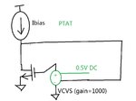
This is my setup and the equation in the pdf file above:

I want to use a temperature-dependent bias current ID (for example, PTAT) to probe VGS behavior in the interested temperature range, by making sure the effect of VDS in this equation can be ignored. However, I found that in using the floating gate test circuit, VDS can vary a lot and in high temperature range, VDS may get closer to VT. If I use the gate-drain connected structure, the VDS always equals to VGS, and thus the VDS>>VT condition cannot be met.
Would anyone give me the suggestion how to correctly setup this test (change the connection, adding the resistor or anything else), in achieving (1) subthreshold operating MOSFETs, by using the drain current to control VGS (2) the drain current can be defined by the user, to be either temperature independent or dependent (3) the impact to VGS from VDS is minimized.
Thank you!
I am trying to use either floating gate or gate-source connected MOSFETs to operate in subthreshold region in the entire temperature range (say 0C to 100C). I want to use the simulated VGS(T) waveform to compare with the model provided in page 10 of https://www.cppsim.com/CircuitLectures/Lecture16.pdf.
This is my setup and the equation in the pdf file above:

I want to use a temperature-dependent bias current ID (for example, PTAT) to probe VGS behavior in the interested temperature range, by making sure the effect of VDS in this equation can be ignored. However, I found that in using the floating gate test circuit, VDS can vary a lot and in high temperature range, VDS may get closer to VT. If I use the gate-drain connected structure, the VDS always equals to VGS, and thus the VDS>>VT condition cannot be met.
Would anyone give me the suggestion how to correctly setup this test (change the connection, adding the resistor or anything else), in achieving (1) subthreshold operating MOSFETs, by using the drain current to control VGS (2) the drain current can be defined by the user, to be either temperature independent or dependent (3) the impact to VGS from VDS is minimized.
Thank you!
