Continue to Site

Welcome to EDAboard.com

Welcome to our site! EDAboard.com is an international Electronics Discussion Forum focused on EDA software, circuits, schematics, books, theory, papers, asic, pld, 8051, DSP, Network, RF, Analog Design, PCB, Service Manuals... and a whole lot more! To participate you need to register. Registration is free. Click here to register now.

Filter Design for broad band

Status
Not open for further replies.

rajesh navagare

Newbie level 5
Joined
Apr 29, 2015
Messages
9
Helped
0
Reputation
0
Reaction score
0
Trophy points
1
Activity points
60
Here, classical filter design method i know but i am not sure about filter design for following situation.

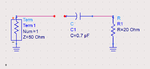
picture is given below for detail where 50 ohm is matched to capacitor and resistance load of 20 ohm, for band of 6 GHZ with center frequency of 5.5 GHz.
 

Attachments

  • Untitled.png
    Untitled.png
    9.6 KB · Views: 62

You can create a bandpass filter by putting in a series inductor. Or as an alternate there is a 2-capacitor bandpass. Perhaps it's not giving away too much if I post these...


These are merely two easy methods. By playing with values you might obtain the specified rolloff curve. Even then there could be a better method.
 
Wideband matching of a reactive load isn't generally possible. I don't see a way to achieve it in the present case.
 
Hello @rajesh navagare ,

For a properly filter design I think you would need 50 ohms in both ports.

Maybe a matching network is what you need.

I often use this calculator to simplify work:

**broken link removed**

You will need to know that 0.7pF are Z_c=1/jwC where w=2pif

BR
 

Status
Not open for further replies.

Part and Inventory Search

Welcome to EDABoard.com

Sponsor

Back
Top