Terminator3
Advanced Member level 3
Scanning patch array antennas become more popular: WiFi, cellular, sensors, etc. all want to receive or transmit signal in certain direction to reduce interference, and able to alter this direction dynamically. I reviewed few papers and datasheets on commercial products, and have many questions and doubts about trends in this area.
Different products require frequencies from 2.4GHz (WiFi) to 9-10 (Satellite) ~70GHz (Sensors).
What can be used to do beam-forming (must be cheap!):
1.Phase shifters. On of the way to form beam in certain direction is to alter phase of individual sub-arrays. This requires expensive phase shifters. Although it can be realized using varactor phase shifters at 2.4GHz or even 5GHz. For higher frequencies it requires expensive RF ICs. One IC for each sub-array.
2. Frequency-scanning arrays. Require too much bandwidth, or too log phase delay lines (losses).
3. Sub-arrays with different phase shifts, which are switched. There are switch IC available up to 5GHz. Higher frequencies - too expensive. But this way looks like the cheapest one.
At higher frequencies, is it feasible to replace SPST switches with FETs and get acceptable performance at least for some applications?
4. Unsure if this idea is correct: What if we make receiving patch array, where each sub-array have separate mixer? Then do phase shifting in time domain on IF low-frequency signal using DSP. After time domain signal from each sub-array is phase shifted, they are all summed up digitally. Could we achieve receiving antenna beam forming using this approach?
For example, we have two sub-arrays (A) and (B). If transmitter is closer to first sub-array (A), then signal at sub-array (B) will have some phase-delay (few GHz signal).
Output of mixer connected to sub-array (B) will have this phase-delay too relative low frequency of MHz. Now if pretty fast ADC is used, waveform from each sub-array can be phase-shifted in time-domain (somehow), then combined. Is it a digital beamforming? It seems the cheapest method (ADC price x sub-array count + DSP price). Only passive (for receive)
Using FET for oscillator, mixer, switch at the same time theoretically can reduce costs (BOM, buying only one component for mass production - higher amounts, lower price). Although can complicate design of mixer and switch.
>>>
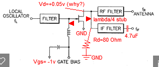
And now FET as resistive mixer question: why resistive mixers are so rarely used? What is the best way to apply RF and LO to resistive mixer? Some authors apply them together, some to gate and drain, sometimes LO is at gate, sometimes at drain. Maybe if LO is applied to gate, biasing requirements are lower, but RF can't be too small. IF RF is applied at gate with good biasing, then LO applied at drain can provide stronger IF output (maybe).
Can we use FET resistive mixer for upconversion? How it compared to Schottky diode in upconversion tasks?
Different products require frequencies from 2.4GHz (WiFi) to 9-10 (Satellite) ~70GHz (Sensors).
What can be used to do beam-forming (must be cheap!):
1.Phase shifters. On of the way to form beam in certain direction is to alter phase of individual sub-arrays. This requires expensive phase shifters. Although it can be realized using varactor phase shifters at 2.4GHz or even 5GHz. For higher frequencies it requires expensive RF ICs. One IC for each sub-array.
2. Frequency-scanning arrays. Require too much bandwidth, or too log phase delay lines (losses).
3. Sub-arrays with different phase shifts, which are switched. There are switch IC available up to 5GHz. Higher frequencies - too expensive. But this way looks like the cheapest one.
At higher frequencies, is it feasible to replace SPST switches with FETs and get acceptable performance at least for some applications?
4. Unsure if this idea is correct: What if we make receiving patch array, where each sub-array have separate mixer? Then do phase shifting in time domain on IF low-frequency signal using DSP. After time domain signal from each sub-array is phase shifted, they are all summed up digitally. Could we achieve receiving antenna beam forming using this approach?
For example, we have two sub-arrays (A) and (B). If transmitter is closer to first sub-array (A), then signal at sub-array (B) will have some phase-delay (few GHz signal).
Output of mixer connected to sub-array (B) will have this phase-delay too relative low frequency of MHz. Now if pretty fast ADC is used, waveform from each sub-array can be phase-shifted in time-domain (somehow), then combined. Is it a digital beamforming? It seems the cheapest method (ADC price x sub-array count + DSP price). Only passive (for receive)
Using FET for oscillator, mixer, switch at the same time theoretically can reduce costs (BOM, buying only one component for mass production - higher amounts, lower price). Although can complicate design of mixer and switch.
>>>
And now FET as resistive mixer question: why resistive mixers are so rarely used? What is the best way to apply RF and LO to resistive mixer? Some authors apply them together, some to gate and drain, sometimes LO is at gate, sometimes at drain. Maybe if LO is applied to gate, biasing requirements are lower, but RF can't be too small. IF RF is applied at gate with good biasing, then LO applied at drain can provide stronger IF output (maybe).
Can we use FET resistive mixer for upconversion? How it compared to Schottky diode in upconversion tasks?