Garurumon
Newbie level 4
Hello!
This is my first post here, and I hope I won't break any rules :smile:.
Anyway, I was trying to build an ESR meter from this LINK, and I was hoping that someone could help me and guide me on how to solve the problems I've encountered.
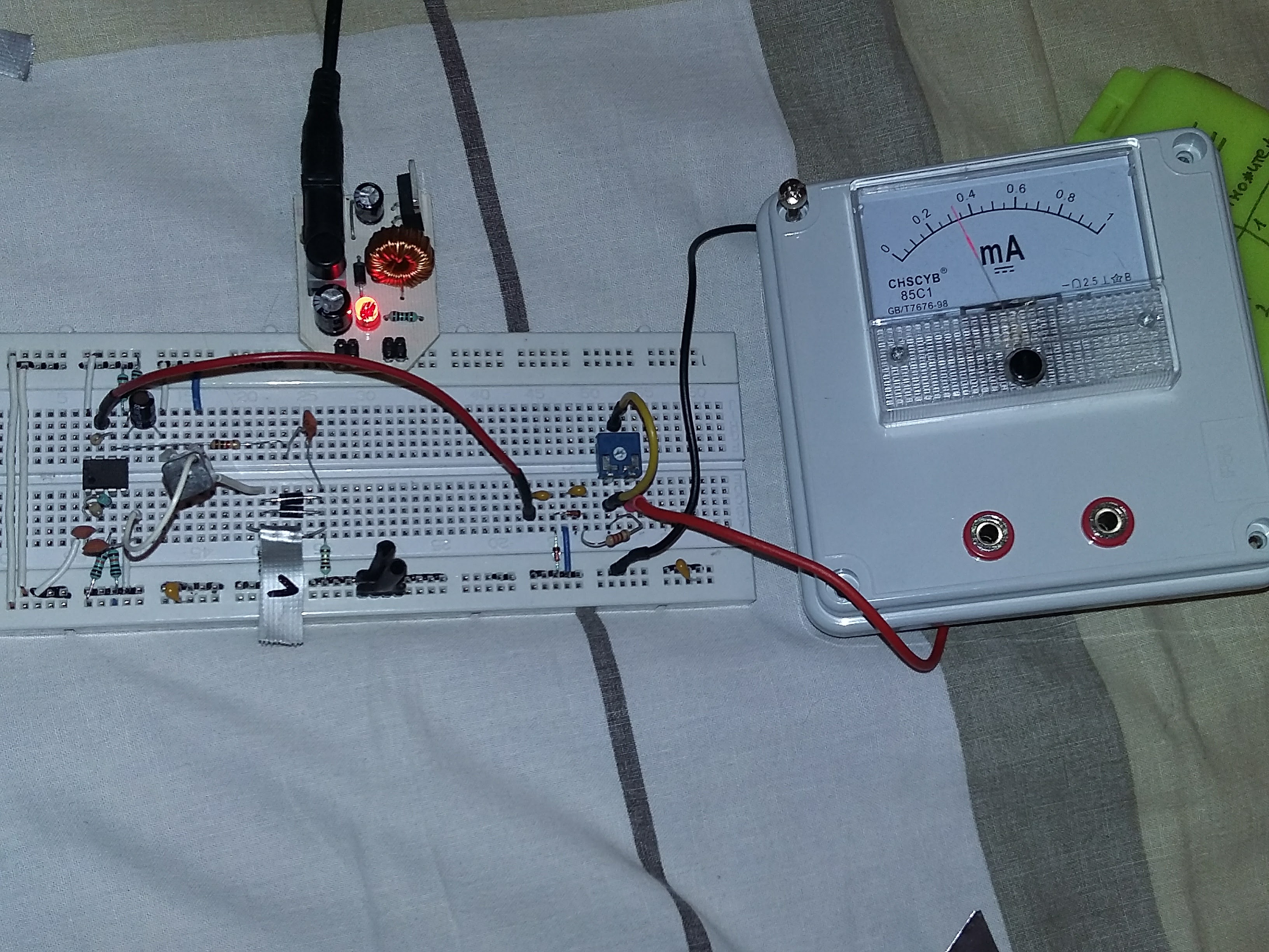
My current setup:

I didn't have the same components, so I made a few modifications: I replaced op amps with LM385 dual op amp, I used xenon flash trigger transformer (HV side as a primary), and a [0-1]mA analog ammeter.
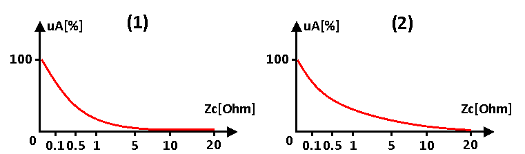
The ammeter is the one that is giving me the headaches, I need to amplify the signal, and I did manage to do it, empirically, but I'm not satisfied with it. The output I get is not linear enough, and the scale saturates already at 5 Ohm input impedance.
I was hoping that someone could point me at which parts of the circuit should I pay attention to get what I want, since I have really little experience with AC signal processing.
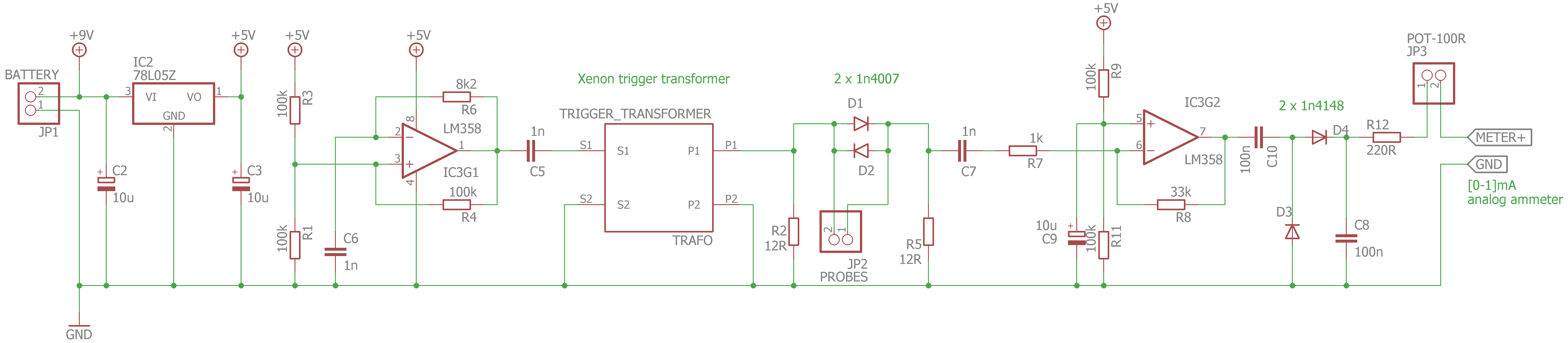
What I did (my schematic):
-I decreased C5 and C7 from 10u to 1n. Made no sense to me, since Xc=1/(2*Pi*f*C), and lowering the C would attenuate the signal, but it worked - I didn't get the detection until I lowered the C significantly;
-I messed with the amplifier gain - settled at 33k (Av=30), for some reason. Giving it lower gain - meter wouldn't go full scale, and giving it a bigger gain - meter wouldn't go to zero with leads shorted;
-I also messed with the output resistor/pot, but that's irrelevant to the problem (I think).
I would like to make the scale somewhat more linear in the range of [0-10] Ohm, and ideally, I wouldn't want to use any more op amps.
Is that doable? Any suggestions? :smile:
This is my first post here, and I hope I won't break any rules :smile:.
Anyway, I was trying to build an ESR meter from this LINK, and I was hoping that someone could help me and guide me on how to solve the problems I've encountered.
My current setup:
I didn't have the same components, so I made a few modifications: I replaced op amps with LM385 dual op amp, I used xenon flash trigger transformer (HV side as a primary), and a [0-1]mA analog ammeter.
The ammeter is the one that is giving me the headaches, I need to amplify the signal, and I did manage to do it, empirically, but I'm not satisfied with it. The output I get is not linear enough, and the scale saturates already at 5 Ohm input impedance.
I was hoping that someone could point me at which parts of the circuit should I pay attention to get what I want, since I have really little experience with AC signal processing.
What I did (my schematic):
-I decreased C5 and C7 from 10u to 1n. Made no sense to me, since Xc=1/(2*Pi*f*C), and lowering the C would attenuate the signal, but it worked - I didn't get the detection until I lowered the C significantly;
-I messed with the amplifier gain - settled at 33k (Av=30), for some reason. Giving it lower gain - meter wouldn't go full scale, and giving it a bigger gain - meter wouldn't go to zero with leads shorted;
-I also messed with the output resistor/pot, but that's irrelevant to the problem (I think).
I would like to make the scale somewhat more linear in the range of [0-10] Ohm, and ideally, I wouldn't want to use any more op amps.
Is that doable? Any suggestions? :smile:
 ).
).