bhl777
Full Member level 6
Hi All, I am building a switchable summer/subtractor circuit using a conventional opamp and MAX4855 SPDT with its integrated comparator.
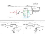
This is my schematic. VDC1 is a user controllable DC input, it will be used to determine the logic high or low of the comparator, and will be used for the summing or subtraction. VDC2 is a second voltage source with a fixed DC level.
I build this circuit on board, VDC1 and VDC2 are in the correct levels, and the opamp itself was tested before connected with the other signals.However, when I connected everything together, and inject a VDC1, comparator shows the correct 1/0 logic, but the opamp does not work properly. The output of the output is either tied high or tied down, instead of generating the proper sum/subtract signal.
Would anyone give me some suggestion, if there is any practical problem in this cirucit? Or how should I investigate the root cause of the built circuit? Thank you!
