Continue to Site

Welcome to EDAboard.com

Welcome to our site! EDAboard.com is an international Electronics Discussion Forum focused on EDA software, circuits, schematics, books, theory, papers, asic, pld, 8051, DSP, Network, RF, Analog Design, PCB, Service Manuals... and a whole lot more! To participate you need to register. Registration is free. Click here to register now.

[PIC] PIC32MX PMP problem, cant get it work

Status
Not open for further replies.

lucadjr

Newbie level 4
Joined
Sep 18, 2016
Messages
6
Helped
0
Reputation
0
Reaction score
0
Trophy points
1
Activity points
53
Hi All!
I cant get PMP working on my pic32mx340f512h. Tryed every example found in internet nothing seems to work to me and cant get change on the I/O pin simulator in MPLABX
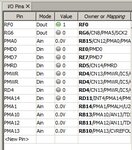
pin i.o.jpg

Code:
#include <p32xxxx.h>                    /* PIC32 Main Library */
#include <plib.h>                       /* PIC32 Prepheral Lib */

#include "config_uc32.h"
#include "delay.h"

#define CONTROL     PMP_ON|PMP_READ_WRITE_EN|PMP_READ_POL_HI|PMP_WRITE_POL_HI
#define MODE        PMP_DATA_BUS_8 | PMP_MODE_MASTER1 | PMP_WAIT_BEG_4 | PMP_WAIT_MID_15 | PMP_WAIT_END_4
#define PORT        PMP_PEN_0        // only PMA0 enabled
#define INTERRUPT   PMP_INT_OFF // no interrupts used

void main(void) {
    SYSTEMConfigPerformance(SYS_FREQ); // FCY = Clock Frequnecy
    INTEnableSystemMultiVectoredInt(); // Interrupt vectoring
    TRISFbits.TRISF0 = 0; //pin RF0 out
    TRISGbits.TRISG6 = 0; //pin RG6 out

    mPMPOpen(CONTROL, MODE, PORT, INTERRUPT);

    LED1 = 0;
    LED2 = 1;

    PMPSetAddress(1); //Set LCD RS control
    PMPMasterWrite(5); // initiate write sequence

    while (1) {
        delay_ms(100);
        LED1 = !LED1;
        LED2 = !LED2;
    }
}

please help!!!
 

Check that the MCU you are using has PWM output supported in the simulator. I know that monitoring output (and input) to peripherals is an area where the simulator often has limitations.
Can you try this on real hardware?
Susan
 
Thanks for reply!!!

Yes i used real hardware with bit-banging and it work properly.
Code:
ENABLE LCD --> RD5 / PMRD 
RS LCD     --> RB15 / PMA0 
R/W LCD    --> RD4 / PMWR  
DATA LCD0_7 --> RD0_RD7 / PMD0_PMD7
than same connections using PMP nothing happen and for this i start monitoring the simulator.

How can i check PWM supported in the simulator? This can have something to do even if those pins are not related to PWM?

Thx again for help!
 

there is also logic analizer wich create graphics with waves ecc and it work good with my heart bit even high fcy while PMP lines sit on 0 (seems to be used even with pwm in internet's picture).

Timing should not be a problem for the display, i follow some books (Di Blasio ecc) where they make examples and timing calculation of the BEGIN, MIDDLE and END PMP_WAIT cycles wich setted to the max will bi enough to drive an hd44780 LCD TYPE.

Anyway i want to learn to use PMP cause this is my middle step before moving to a graphic display and i want to understand it, and the idea that something is not working how should be dont let me go trough.

Cant figure out wht is the problem... PLZ help!
 

Although the problem isn't PWM related, it could be that the parallel bus port isn't fully modeled in simulator. I'm also not sure if the simulator (presumed it does model it) will show you bus operation in the static pin state. Bus access is only lasting a few clock cycles.

Generally, I don't see the purpose of parallel bus port for interfacing a very slow peripheral like LCD display. You'll face serious difficulties to slow it down to the required LCD timing.

- - - Updated - - -
Thank's for the information.
In this case, you'll want to check if your PMP programming works with real hardware, e.g. by connecting an oscilloscope.
 
Thx for help!

Unfortunally i dont have an oscilloscope, the only thing is that with same connection bit-banging is working.
To be sure about the timing i also setted FPBDIV = DIV_8 to set PBClock low as possible.

Could someone of you please make a little PMP program just to check if really simulator I/O pins or lagic analizer doesent work with PMP??
To me seems strange that even the setting of PMA0 still analog input as show the picture i attached.
Thx anyway!
 

Apologies to all - I misread the OPs question as PWM related, not PMP!
Susan
 

Status
Not open for further replies.

Similar threads

Part and Inventory Search

Welcome to EDABoard.com

Sponsor

Back
Top