angy
Full Member level 3
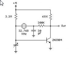
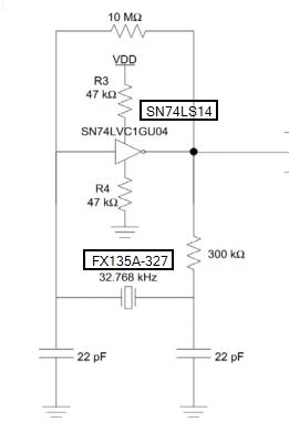
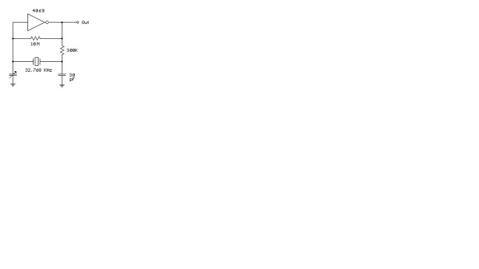
I have a crystal oscillator part no :fx135a-327 . i was looking into its datasheet for the test circuit but it does not have.So please help me out with some simple test circuits .
I want to calculate frequency stability, Rise time Fall Time,Startup time etc.
What is the Input to be given >
I want to calculate frequency stability, Rise time Fall Time,Startup time etc.
What is the Input to be given >
Last edited:
")