Continue to Site

Welcome to EDAboard.com

Welcome to our site! EDAboard.com is an international Electronics Discussion Forum focused on EDA software, circuits, schematics, books, theory, papers, asic, pld, 8051, DSP, Network, RF, Analog Design, PCB, Service Manuals... and a whole lot more! To participate you need to register. Registration is free. Click here to register now.

[SOLVED] 10 days of anguish - the story of my first repair of consumer electronics

Status
Not open for further replies.

aromring

Newbie level 4
Joined
Apr 29, 2016
Messages
6
Helped
1
Reputation
2
Reaction score
1
Trophy points
3
Activity points
139
Day 0:
It's late April and a cute coworker of mine is in despair. She brings her broken Philips DVD player (DVP642, like this:
http://salestores.com/philip27.html)

to the office in hope that someone might help her. What's so special about 11-year old DVD player? - you might ask. Just throw it away and buy a new one; these are not expensive, right? Well, what's special about this particular player is the fact that it's easily hackable. She entered a special code years ago, made it region-free, and ever since can play movies from all over the world in both NTSC and PAL formats. It's particularly golden for someone like her who likes foreign movies. One of such rare foreign discs is now stuck in the drawer which doesn't want to open. "Help me" - she pleads - "at this point I don't care if you have to break apart the player, just get my disc out!". All right, since I have a few simple tools in my office I sit down, unscrew the drawer, and after 1 minutes figure out how to open it manually by shifting a white plastic guide at the bottom. "Here it is" - I hand over the disc.

That would be over for most people, but not for me. About a week ago I passed the final exam in the last part of the 3-part on-line course in basic electronics
(
**broken link removed**
) - my new hobby. I am so empowered and bursting with circuit theory that feel a primal need to turn all this new knowledge into practice. "Tell you what" - I tell my colleague - "I'll fix your player at no charge. I truly need to practice my new skills in the real world. Your broken Philips is an excellent object!" Fortunately, she agrees and I take the player home.

Day 1:
From what I gather, the DVD player worked fine for 10 years, then started acting up: the drawer would open only half way, for example. Sometimes it wouldn't turn on. Finally, it completely gave up with the dreaded blinking power light. Even the front display stays blank.

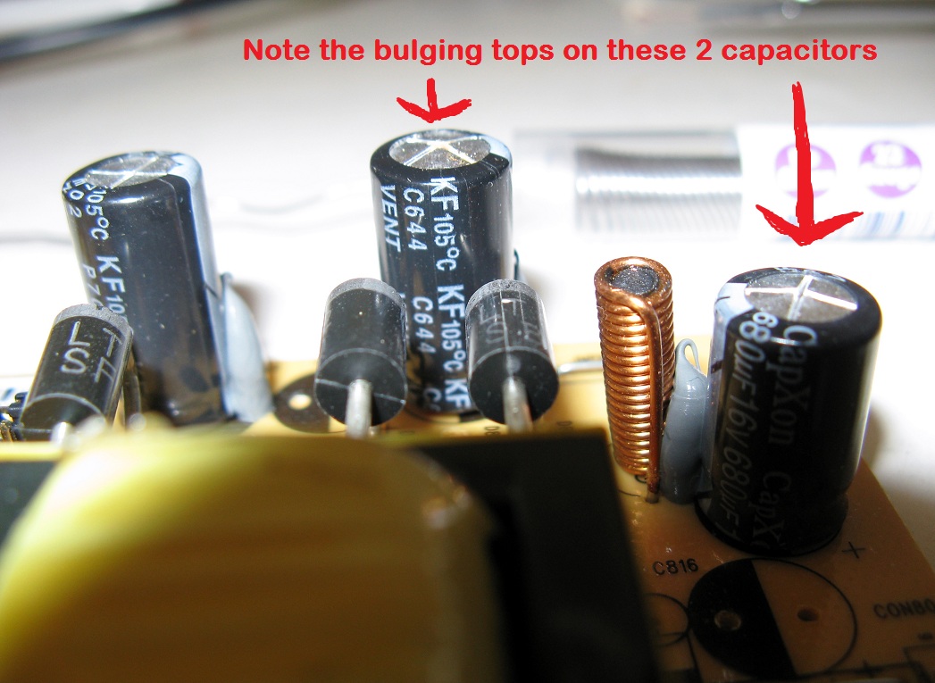
Initially, the repair seems easy. I already know that the main reason why consumer electronics breaks is limited life of electrolytic capacitors, especially in high temperature environment:


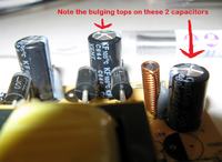
[from www . markdigital . com/wp-content /uploads /2011/02 /bulging_capacitors.jpg]

9247460700_1473572285.jpg


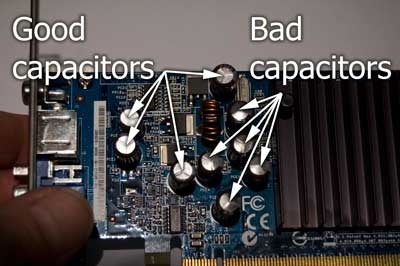
[from www . geeksinphoenix .com /blog /images /Computer_Randomly_Freezes_Up_01.jpg]

The electrolyte gradually dries up, or boils out, the ESR shoots up, while capacity dives down. Often this happens because manufacturers place capacitors next to hot elements, like transistors or power resistors… No, it's not about bad design, it's all about obsolescence _by_ design. More on this later.

I google DVP642 up and sure enough, here pops up this YouTube video:


Turns out, a bad 1000 microF capacitor, C316, in a switched mode power supply is the culprit responsible for failure of many DVP642's. I take a closer look at the power supply board it's LVP103850. C316 looks fine. It's C310, a 470 uF capacitor on the +12V line that is bulging. "Easy!" - I think. But when I replace it with a new, good one and… the DVD player still doesn't turn on. Hmmm, it's more complicated than I thought.

To be continued.
 
Last edited by a moderator:

Day 2
Time to learn more about switched mode power supplies. Indeed, capacitors fail most often, but trouble may be caused by bad diodes, transistors, and so on. I desolder C316, just in case, and replace it with a new capacitor with higher voltage rating. Fortunately, I find service manual for DVP642 with all schematics View attachment Philips_DVP630_632_642.pdf from here:

https://www.eserviceinfo.com/downloadsm/60875/PHILIPS_DVP630, DVP632, DVP642.html

which is like a gold mine to me, saving me a lot of tedium in tracing all connections by hand. Another lucky thing is the excellent M8 Transistor Tester (**broken link removed**) I've built from a kit about one year ago, since it lets me test caps in the circuit. Thus I find a few more aged caps, as expected, in power supply as well as dried out filtering caps in the motherboard. I replace all, but the bloodydamn thing still doesn't work. OK, I move to diodes - I use my multimeter to test each one in circuit. Bingo! I find one of the rectifier diodes, D301, to be shorted. I have quite a few 1N4007's in my collection of parts, so replacement is a breeze. I put the power supply board back in, turn it on - it works! The front display comes up, DVD drawer opens - cool! I load a test video and watch it for a few minutes.

It's Friday night, so the good news for my coworker will have to wait till Monday. With a warm, good feeling I focus on my other electronics projects. My first repair - I fixed it!

Or so I thought…

To be continued
 

Good story i look forward to the rest.
 

I assume that you already have repaired it..........;-)

Anyways, a good troubleshooting story is always compelling, one can always learn something from someone else's travails.

If it is good, I can also share some of my battle scars.
 

Day 3
First thing on Monday morning, with a big smile I announce to my coworker: "It's fixed". I connect it to a flat panel TV in the conference room expecting to see the same test video I saw on Friday… and nothing works! Connections? No, these are fine. Besides, the DVD drawer doesn't open and power light is off. :( What the <bleep>?! Talking about the ultimate manifestation of the Murphy's Law. "Well", she says, "looks like this player is heading to its final destination: garbage can." I'm quite embarrassed, but answer this: "Oh no, I don't give up so easily. Now I HAVE TO repair it, regardless of cost. It's in my nature to push back twice as strong when pushed!"

Back at home, I start systematic testing of the power supply board, element by element. Almost instantly, my attention focuses on the same +12V power line, as well as -24V which originates from the same secondary coil. My multimeter shows only +8.4V and -20.4V, respectively. Why so low? It can't be the transformer, because it feeds the other two lines, +5V and -12V, that are perfectly OK.

Days 4-7
I am so fixated on the underpowered +12V/-24V line, that I spend every available minute examining it in detail. I desolder and test every single diode attached to it. They all are fine. Same with resistors. Examine all lines leading from mains to on/off switch, back to SMPS, in and out. All OK. The only logical explanation seems to point back at the transformer. But again, the +5V supplied by the same transformer is fine, supplying even slightly higher voltage of +5.23V! It's a mystery. V1/V2 = N1/N2, right? Ratio of transformed voltages equals the ratio of coil windings, right? And the latter have not changed, right?

Often I get good ideas under the shower, or while falling asleep. This time it occurs to me while I shampoo my hair that perhaps the N2 HAS changed: the +12V/-24V might have shorted internally in such a way that it's number of windings is now effectively lower. This is still very bizarre and improbable. The player did work on Friday, after all. Hence, why would such shorting occur on Monday morning - right then and there? Still, I don't have any other explanation. That's bad news because transformers are custom-made for SMPS manufacturers, so I can't just pop the old one out and replace it with another. Unless, I find another board like this. Hmm… Thus, I search the Internet stores and, incredibly, I find one on-line store in Canada that has refurbished SMPS board with the same model number! Let me find it… here: https://alfa-electronique.com. It's the last one in stock, so I order it promptly.

Bah! Two weeks minimum shipping time. Damn.

To be continued
 

Hello aromring,
Your story reminds me so much of "The Serviceman's Log" written every month in Silicon Chip magazine. Well written my friend :)
I would ensure that every cap with the same brand be replaced, regardless if they look or measure ok. The CapXcon brand are notorious for leakage and bulging. Also make sure you replace them with 105 degree types.
You need to do a punch-through test on the diodes, to ensure they are not leaky, though its not an absolute test. As shown down the bottom of the post https://www.electronic-circuits-diagrams.com/forum/viewtopic.php?f=3&t=6474
Is D301 similar to the diodes shown in your first photo? If so, then an 1N4007 won't have the current rating required for your circuit. The diodes I see in your photo seem to be at least 3 Amp types.
You can always place a dummy load across your 12V rail by using a 12V filament light globe from a car, but make sure you isolate the rail from the rest of the circuit. With the dummy load connected you can determine if the 12V rail measures correctly.
If you find that the rail is stable with a dummy load connected, then the problem lies further down the line. I would check any Voltage Regulator IC's that are fed from the 12V supply.
As for the -24V line, you can use a 24V truck light bulb as a dummy load to do a similar check as above.
Transformers rarely give problems, and unless you have a shorted-turns tester suited for the switching frequency, there's no other way of testing it, short of replacement, to which you've proceeded to do. Though be prepared to possibly be let down when you fit the new tranny.
Please continue your story, as it is extremely interesting and well written.
Regards,
Relayer
 
Last edited:

Days 8-9
Well, I am not going to just sit and wait for two weeks. The curiosity takes over. Since the "patient" is already on the "operating table" I explore other circuits. I check the remote's IR signal and the associated circuit response - it works. Now, I recall that the digital display does not work at all. Well, well, this is where the -24V line connects. The LED display is managed by the HT16512 controller, so I probe it here and there, and it all seems in working order: it's powered by the healthy +5V. I wonder how it communicates with the motherboard? Through RB502. Curious, I connect my oscilloscope to the communication lines and … see nothing. What? Turn on and off - nothing. Both the LED board and motherboard do receive healthy +5V, on entry, so what's going on? All right, I am checking VCC on HT16512 - OK, checking VDD on ES6698 - the main microprocessor - not OK. Wow, wow, go back: "not OK"? Yes, all of CPUs power pins read 0V. How? Check motherboard entry point: still +5V!

Aha! There must be a problem in between motherboard's RB302 connector and the CPU. [Somehow, that reminds me of the PEBKAC acronym (look it up :) ] With renewed vigor I start checking all the joints and during these searches I accidentally touch something and in the corner of my vision I see the DVD laser diode coming alive for a brief moment. Wait, wait, what was that? What did I touch? Ah, it's one of the filtering capacitors near RB302 - I replaced all of them on day 2. All replacements were new and thoroughly tested by me for capacity and ESR. How could one be bad? The player worked on Friday, after these replacements, right? No, it's not bad, further testing reveals that I have to tilt it certain way to either open or close the power connection to the motherboard internals. Interesting…

I unscrew the motherboard again and look underneath. Everything looks OK. So I dig out my USB microscope and carefully check all connections to the guilty cap. I see it: one of the copper tracks is slightly detached from the surface. Impossible to notice without a microscope. The cap is still connected, but tilting detaches/reattaches its track from the rest of the circuit. Wow.

160507110901946598.jpg

So this was the source of this bloodydamn problem all along. I created this monster. While fixing the original problem - bad cap and diode in SMPS - I followed the advice of checking/replacing all other caps on power lines. Inadvertently, while soldering this particular new cap, I must've pushed it too hard detaching its circuit track. On Friday, it was tilted the right way and all connections were fine. While I was driving on Monday morning (and I'm a rough driver) it titled the other way breaking the +5V line.

Holy cow.

I've soldered an extra wire on top the broken track, to ensure connection. That was it, a very short piece of wire to finally fix everything.

1605071309238168056.jpg

It also solves the mystery of low voltage on the +12V/-24V line. It is the +5V line that is monitored by the SMPS circuitry via the H11A817 optocoupler. Therefore, if +5V is consumed the transformer must work harder to meet the demand. Conversely, open +5V makes transformer's work easy. Consequently, the power invested into the other line, the +12V/-24V, follows the same trend.

Day 10
I bring the repaired DVD player to the office, quietly, connect it to the TV in conference room. It works, phew! Only then I call my coworker - she's all happy.

Photo May 09.jpg
Photo May 09_2.jpg
 
  • Like
Reactions: Relayer

    Relayer

    Points: 2
    Helpful Answer Positive Rating
Epilogue
She's happy until this day, since the player works perfectly OK since my repair back in May.

Now, on day 1 I promised to write about the obsolescence by design. Yes, it concerns one cap, C309, in the primary circuitry of the SMPS: the manufacturer placed it precisely in between transistors and power resistor, making sure they all touch. Both transistors and the resistor get very hot during normal operation, thus this cap also gets hot and cozy. As you all know, electrolytic caps are sensitive to high temperature failing faster when hot… So there you have it: obsolescence by design. Dirty low blow.

IMG_8563.jpg
IMG_8565.jpg
 

Well done aromring ;-)
Excellent story and good trouble-shooting...
Glad it all worked out for you, and you made a person extremely happy. Not to mention your own gratification in solving the mystery. :grin:
Regards,
Relayer
 

All is well that ends well. Cu foil tends to peel off from the single sided paper phenolic boards and removing big components is a real hassle. But in general, philips circuits and boards are somewhat better designed and more repair friendly.
 

Well done aromring ;-)
Excellent story and good trouble-shooting...
Glad it all worked out for you, and you made a person extremely happy. Not to mention your own gratification in solving the mystery. :grin:
Regards,
Relayer

Thank you very much for kind words, awesome troubleshooting advice, and the excellent multimeter tutorial.
To answer your question, the first photo of caps is not mine; I pulled it off the Internet for illustration. The SMPS diodes were of the 1N4007 type.
 

I like post #9, a good practical design tip.
 

And she comes in Monday morning and says "Oh - I got a streaming video player, I don't watch DVD's any more" :) :) :)
 

Status
Not open for further replies.

Part and Inventory Search

Welcome to EDABoard.com

Sponsor

Back
Top