Continue to Site

Welcome to EDAboard.com

Welcome to our site! EDAboard.com is an international Electronics Discussion Forum focused on EDA software, circuits, schematics, books, theory, papers, asic, pld, 8051, DSP, Network, RF, Analog Design, PCB, Service Manuals... and a whole lot more! To participate you need to register. Registration is free. Click here to register now.

Help in understanding PNP Transistor as a switch.

Status
Not open for further replies.

Bjtpower

Full Member level 5
Joined
Dec 24, 2015
Messages
297
Helped
2
Reputation
4
Reaction score
2
Trophy points
1,298
Activity points
3,893
Dear Friends

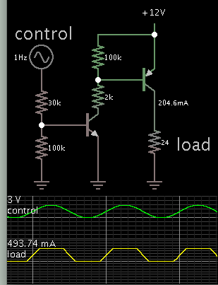
I want to use the PNP Transistors as a switch which can be CONTROLLED from a uControllers of 3.3V/0V.

I am applying a +12v at the Emitter..
i want to use the Pull up resistor at the base.

I am confused for
1)If High Signal(3.3v) From uCONTROLLERS then what will be the output..??
2) If 0v from uCONTROLLERS what will be the output?

Driving a load at the collector to Gnd..

Pls help with the base resistor calculations as pull up resistor calculation for 500mA OF CURRENT thru the bjt
 

With 3.3V from your micro on the base the emitter can only be 3.3+- .8 or so, i.e. 2.5 or 4.1V or you will destroy the transistor.
If you want your emitter to switch , say +12V/0V then the first stage is to amplify the 3.3V. When its delivering current the output voltage will be less then 12V
Frank
 

Hi,

PNP in highside (+12V) is more difficult.
Why not NPN in low side (GND)?

Klaus
 

My application circuit is here..

it is just a Task that i have to do it with the PNP Transistors.
How i can drive it through uControllers..??
The voltage at the Emitter is +12v

Kindly update the same and revert.
IMG_20160907_193153.jpg
 

Hi,

your circuit doesn´t work this way!
The voltage at the Emitter is +12v
And therefore the voltage at the base needs to be about +12V of OFF and about +11.3V for ON. That´s the difficulty. (Voltages are not absolute! They vary with supply voltage and V_BE of the transistor)

*****

Any load can be switched low side or high side. Low side is easier. Why do you insist in high side switching and PNP?

Klaus
 

Then, How i can i drive it with the +12V..

Are there any other ways..??

Pls suggest
 

3V controls an NPN, which in turn controls the PNP. Adjust values so that the PNP provides 500mA to the load.

2403127600_1473265290.png


The 100k resistors are a good idea to include.
 
If using the PNP as a switch then the value of the 2K resistor in Brad's circuit should be selected so that the PNP base current is at least 1/10th of the collector load current to insure that the PNP is fully on and saturated when switched.
Basically this means the 2k resistor should be no larger than 10 times the load resistance.
Thus the 2k resistor should actually be ≦240Ω and the 30k resistor should be ≦1.3kΩ for the 24Ω load.
 
Hi,

Why don't you a simple internet search "microcontroller relay" ?

reltest.gif
Where it shows "5V" connect your 12V.

I assume you find more than 100000 of these schematics in the internet.

Klaus
 

Attachments

  • Download.png
    Download.png
    3.3 KB · Views: 111
Status
Not open for further replies.

Similar threads

Part and Inventory Search

Welcome to EDABoard.com

Sponsor

Back
Top