Continue to Site

Welcome to EDAboard.com

Welcome to our site! EDAboard.com is an international Electronics Discussion Forum focused on EDA software, circuits, schematics, books, theory, papers, asic, pld, 8051, DSP, Network, RF, Analog Design, PCB, Service Manuals... and a whole lot more! To participate you need to register. Registration is free. Click here to register now.

Can we use one op-amp to achieve the non-inverting V sum and buffer for high Iout

Status
Not open for further replies.

bhl777

Full Member level 6
Joined
Sep 30, 2008
Messages
363
Helped
0
Reputation
0
Reaction score
0
Trophy points
1,296
Activity points
5,140
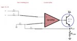
Hi All, I am designing a circuit to achieve the non-inverting sum and current buffer. We can use two op-amps for each process, like this picture.

ONE OPAMP.jpg

I am wondering is it possible to merge them together, by just one op-amp to achieve the same goal? No high precision is required in my application. Thank you!
 

Hi,

You may connect the input resistors directely to Opamp2.
Maybe you need an additional resistor to GND

(I don't think you need the gain, that the first Opamp generates....but only you know the specifications)

Klaus
 

Hi,

You may connect the input resistors directely to Opamp2.
Maybe you need an additional resistor to GND

(I don't think you need the gain, that the first Opamp generates....but only you know the specifications)

Klaus

Hi Klaus, is this what you are talking about? Thank you!
All resistors can be tuned to generate the target output.
ONE OPAMP2.jpg
 

Hi, can anyone give me some suggestion how to choose a discrete FET for my application? If the Vin and VCC are both 5.5V, and Vout can go up to 5V, I guess a BJT cannot be used.
My questions are:
(1) if I want to choose a MOSFET to operate in its triode region (current capability around 50mA), should I use PMOS or NMOS?
(2) I found most of the discrete FETs are used as switches. Can these products also be used in their triode region as the variable resistors?
ONE OPAMP3.jpg
 

Attachments

  • ONE OPAMP2.jpg
    ONE OPAMP2.jpg
    68.6 KB · Views: 61

Hi,

We can not know the values of your inputs, you have to give them...

Therefore I only can assume that you rather should connect the GND-resistor to IN+.
For calculation we need your values..

Mosfet: voltage as you need plus some overhead, the same is with current, power: worst case = U x I, V_gs_th < 2.5V

Klaus

Thank you Klaus. Sorry for the confusion. My V1 is around 1.2V and V2 is 3.2V. My target is to achieve a Vout=5V.
(1) Sorry I do not understand your advice "rather should connect the GND-resistor to IN+". Would you give me a picture of the connection?
(2) Can I use a PNP device like MPSA92 in the current buffer? I am using the general opamp in LTC1541.
 

Hi,

My V1 is around 1.2V and V2 is 3.2V. My target is to achieve a Vout=5V.
You build a current source... what do you mean with 5V? 5V is no current.

****

1) first you need to tell the relationship between input voltage and output current.

******

2) we don't know what circuit you need. With a NPN you create a low side current source. With PNP and some changes you can build a high side current source.

Klaus
 

Hi,


You build a current source... what do you mean with 5V? 5V is no current.

****

1) first you need to tell the relationship between input voltage and output current.

******

2) we don't know what circuit you need. With a NPN you create a low side current source. With PNP and some changes you can build a high side current source.

Klaus

Thank you Klaus. Actually I am trying to use discrete opamp and PNP or NPN to build a regulator, such as an LDO. The load of the circuit is just a pure resistor. The only difference between this circuit and an conventional LDO is that its Vref should be a sum of V1 and V2, instead of a 1.2V from a reference circuit. If we assume the current capability is within the limit for the PNP/NPN, would you teach me how to build this regulator?
 

Hi,

Sorry, my mistake.
Your circuit shows a voltage regualtor. Use the bjt circuit of post#4
So indeed it can work.

But you need to specify the characteristic.
U_out = gain_x * (U1 + U2)

Then the feedback resistors have to be calcualted like for an non-inverting opamp circuit, but with doubled gain: (gain_n = 2 * gain_x.)

*****

OPAMP:
* You need to select an OPAMP which is capable for common_mode_input_voltage_range: 0...(V1 + V2)/2
* V_out (and supply) for an output_voltage_range of 0.5V ... V_load + 1V

****
I recommend to use a simulation tool. There are many free tools around.

Klaus
 
  • Like
Reactions: bhl777

    bhl777

    Points: 2
    Helpful Answer Positive Rating
Status
Not open for further replies.

Similar threads

Part and Inventory Search

Welcome to EDABoard.com

Sponsor

Back
Top