Continue to Site

Welcome to EDAboard.com

Welcome to our site! EDAboard.com is an international Electronics Discussion Forum focused on EDA software, circuits, schematics, books, theory, papers, asic, pld, 8051, DSP, Network, RF, Analog Design, PCB, Service Manuals... and a whole lot more! To participate you need to register. Registration is free. Click here to register now.

[SOLVED] How reduce transient voltages with a transistor+zener+resistor regulato?

Status
Not open for further replies.

JohnJohn20

Advanced Member level 4
Joined
Feb 2, 2012
Messages
111
Helped
0
Reputation
0
Reaction score
0
Trophy points
1,296
Activity points
2,377
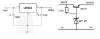
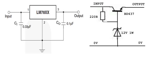
Hi. I want to regulate a 45VDC unregulated power supply down to 300mA at ~12V. I was going to use a LM7812 until another member pointed out they have a max Vin of 35V. My plan was to use the circuit shown on the right:

The LM7812 datasheet says:
30. CI is required if regulator is located an appreciable distance from power supply filter. In my case the main rectifier bridge and capacitor are less than 100 mm from the regulator.
31. CO improves stability and transient response.

Would it help to include capacitors like this?
Are there any other tricks to make this regulator give a smooth DC voltage when the input voltage can vary from 32 V - 45 V (due to factors like switched high current loads up to about 15A) and is quite likely to have spikes and ripples?

Thanks. Chris.
 

Hi,

45V and 300mA gives 13.5W. This is a lot of heat.
12V x 300mA = 3.6W is dissipated in your application
and (45V-12V) x 300mA = 9.9W is dissipated in the linear regulator circuit. (= Wasted power, unnecessary heat)

You could just use a single zener (maybe 15V) in front of the 7812 to drop down the 45V to 30V.

The dissipation in the zner is 15V x 300mA = 4.5W
Then the dissipation in the 7812 is (30V-12V) * 300mA = 5.4W

You see with linear regulators, or zeners or transistors you just spread the dissipated power to different devices, but the sum is the same.

I recommend to use a swtiching regulator. Step down, buck. They usually have an efficiency of 80% or better.
So if your application needs 3.6W, it draws only 4.5W from the supply and wastes 0.9W (before it was 11 times more wasted power)

Besides of the wasted energy, you may use a smaller power supple (not in your case) or it increases battery lifetime (not in your case) .
And 13.5W of heat is really a lot. You need a relatively big heat sink to keep temperatures below 50°C.

Klaus
 
Hi,
45V and 300mA gives 13.5W. This is a lot of heat.

I recommend to use a swtiching regulator. Step down, buck. They usually have an efficiency of 80% or better.
Cheers Klaus. The heat is a big issue. And ugly. It is a compromise between simple and elegant. For the moment I will have a second small 12V PSU in the case. Simple and efficient. Still a bit ugly though.
 

Would you consider voltage reduction by charge pump? It has some reactive drop, some resistive drop.

C1 charges and discharges in such a way that power goes to the output during both halves of the cycle. Some power is wasted because the transistors turn on partially. Heating effect should be tolerable as current is drawn from the supply during a fraction of the cycle.

This is my simulated experimental project. It is not tested with hardware. I don't know how well it would work for you.


Would you consider voltage reduction by charge pump?
Hi Brad. Yes I would if I was looking to do something practical from an interest perspective.

But, I have no 40V clock signal. Be more straight forward if I have a clock to set it up to control Vout by straight PWM.

This concept of this circuit is more suited to increasing (pumping up) the voltage rather than reducing it. Right?
 

But, I have no 40V clock signal. Be more straight forward if I have a clock to set it up to control Vout by straight PWM.

A classic astable multivibrator could be suitable. Two transistors, two capacitors, and a few resistors.

Or...
Place an NPN transistor so it pulls the PNP bias to ground. Then a low voltage is sufficient to turn on the NPN. Arrange a suitable resistor network at the PNP bias terminal.

This concept of this circuit is more suited to increasing (pumping up) the voltage rather than reducing it. Right?

Yes, the charge pump is often found in voltage multipliers. My circuit is the result of playing with values. A small capacitor is exposed to a high voltage briefly. It then empties the stored energy into a large capacitor, whose voltage is raised a little bit. The method is not the most efficient.

You need a way to adjust duty cycle. This may not be easy. There could be a way with an op amp and 555 timer IC.

For efficiency look into using a buck converter (per post #2).
 

The LM7812 datasheet says:
30. CI is required if regulator is located an appreciable distance from power supply filter. In my case the main rectifier bridge and capacitor are less than 100 mm from the regulator.
31. CO improves stability and transient response.

Would it help to include capacitors like this?
Are there any other tricks to make this regulator give a smooth DC voltage when the input voltage can vary from 32 V - 45 V (due to factors like switched high current loads up to about 15A) and is quite likely to have spikes and ripples?

Hi,

I think it pretty much always helps to bypass every IC to some degree or other, others will disagree probably. It doesn't do any harm to put the input and output capacitors on the 7812. Probably can omit inpout one due to 100mm, but personally wouldn't omit output one ever, that is what helps with load changes, although if up to 15A best to check line and load regulation specs of datasheet and related graphs, + oscilloscope snapshots if included, in datasheet to grasp what IC can and can't cope with well.

Could parallel a bulk and a high frequency low value cap at either side, rather than just one. I use 1 to 10 uF on output depending on application in parallel with a 100nF ceramic.

Adjustable regulators can obtain improved regulation, according to several app notes, by paralleling a voltage reference with the output, never tried it so couldn't confirm if it works as I think references don't handle load changes well as that isn't their function.

If the 7812 will see large input range of any value, I'd put a larger cap like a 10 uF on the input too.

But I agree with the experts opinions in previous posts, ditch the linear regulator (think of them as voltage dropping resistors with large dropout voltages) and use a switching regulator if possible.
 
Could parallel a bulk and a high frequency low value cap at either side, rather than just one. I use 1 to 10 uF on output depending on application in parallel with a 100nF ceramic.

Hi D. Thanks. I have seen capacitors in parallel circuits before but couldn't see the point.
 

Status
Not open for further replies.

Part and Inventory Search

Welcome to EDABoard.com

Sponsor

Back
Top