Continue to Site

Welcome to EDAboard.com

Welcome to our site! EDAboard.com is an international Electronics Discussion Forum focused on EDA software, circuits, schematics, books, theory, papers, asic, pld, 8051, DSP, Network, RF, Analog Design, PCB, Service Manuals... and a whole lot more! To participate you need to register. Registration is free. Click here to register now.

Open loop gain simulation question

Status
Not open for further replies.

tenso

Advanced Member level 4
Joined
Feb 18, 2015
Messages
110
Helped
3
Reputation
6
Reaction score
2
Trophy points
1,298
Activity points
2,399
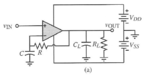
I was simulating the open loop gain of an op amp circuit and I used the following setup measured in Allen's book.
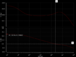
The resistance and cap values are chosen to be large so that the 3dB frequency is low. Sure enough, it gave the expected value of my open loop gain of around 70 dB.
When I get rid of the feedback path and ground the inverting pin, I am getting a gain of around 44dB when I run an AC analysis. Why the difference and shouldn't open loop gain be measured with no feedback?
 

Attachments

  • Capture.PNG
    Capture.PNG
    27.3 KB · Views: 220

When I get rid of the feedback path and ground the inverting pin, I am getting a gain of around 44dB when I run an AC analysis. Why the difference and shouldn't open loop gain be measured with no feedback?
I am afraid that without DC feedback there will be no correct DC operational point within the linear range of the amplifier - unless you perform a good input offset compensation.
 

I am afraid that without DC feedback there will be no correct DC operational point within the linear range of the amplifier - unless you perform a good input offset compensation.

Hi thanks for the time to answer my question. When I did the AC analysis I just set the AC magnitude to one and did a frequency sweep to get the open loop response. I didn't apply a DC bias. I looked up the SPICE manual and it says when doing AC analysis, it does DC operating first and then linearizes everything with the small signal model.

Does Spectre put a DC bias value on its own? If I run the simulation with a bias on my inverting input and no feedback, will that work?
 

No - I don`t think so.
For simulating the open-loop gain without any feedback, you should perform a DC sweep at first.
For this purpose, ground the non-.inv. input of the opamp and connect a DC source to the inv. input.
Perform a DC sweep (between - 10mV and + 10 mV) in µV steps and find the input DC voltage which gives you zero DC output voltage.
Now - this offset correction voltage remains connected to the inv. input and you can connect an ac voltage source to the non-inv. input for finding the open-loop gain.
 
  • Like
Reactions: AMSA84

    V

    Points: 2
    Helpful Answer Positive Rating

    AMSA84

    Points: 2
    Helpful Answer Positive Rating
The usual way to setup the DC bias is to keep the negative feedback path and filter it with a very large time constant, e.g. capacitor of 1F, 1000F, whatever is appropriate.
 
No - I don`t think so.
For simulating the open-loop gain without any feedback, you should perform a DC sweep at first.
For this purpose, ground the non-.inv. input of the opamp and connect a DC source to the inv. input.
Perform a DC sweep (between - 10mV and + 10 mV) in µV steps and find the input DC voltage which gives you zero DC output voltage.
Now - this offset correction voltage remains connected to the inv. input and you can connect an ac voltage source to the non-inv. input for finding the open-loop gain.

I did the DC sweep method to calculate the offset voltage as the first part of a tutorial I am following. The tutorial also mentioned that you could estimate the open loop gain by looking at the slope of Vout vs Vin, which I did. This was in agreement with the value I measured with the RC setup in the picture in my first post.
I did the offset correction you mentioned here and the open loop magnitude was correct! But I don't understand why it worked.

Why is it that the offset correction is needed to measure the open loop gain when there is no feedback while the RC feedback setup needs no such correction? Thanks for the help!
 

Your first circuit sets the DC bias from the negative feedback through the feedback network, which gives a closed loop gain of 1 for DC.
Thus the output DC bias point is essentially equal to the small input offset value (typically no more than a few mV).

Without that feedback the op amp output will likely saturate at one of the rails due to the high open loop gain, which amplifies the small input offset that all op amps have.

Why do you want to simulate with no feedback?

Yeah I went back and looked at the setup again and now it makes sense. thanks for the help.

I have one more question and I hope you or one of the mods here could help me answer. How is stb analysis any different than the ac analysis I did here for measuring the open loop gain? using stb I got the same value as I did for the ac analysis but stb calls it 'loop gain'. Is the a naming issue? Because I thought loop gain referred to the beta A(s) term (beta * Ao for closed loop DC gain).

The usual way to setup the DC bias is to keep the negative feedback path and filter it with a very large time constant, e.g. capacitor of 1F, 1000F, whatever is appropriate.
thanks I got it. could you answer the question about stb analysis?
 

I think, the usual terminology is

Ao = open loop gain
Ao*β = loop gain
α*Ao/(1+Ao*β) = closed loop gain (operational gain of the amplifier with feedback)
 
  • Like
Reactions: LvW

    LvW

    Points: 2
    Helpful Answer Positive Rating
I think, the usual terminology is

Ao = open loop gain
Ao*β = loop gain
α*Ao/(1+Ao*β) = closed loop gain (operational gain of the amplifier with feedback)

yes, you are right. So is stb measuring Ao or Ao * beta. Because my simulation tells me it is Ao
 

The STB analysis linearizes the circuit about the DC operating point and computes the loop gain, gain and phase margins (if the sweep variable is frequency), for a feedback loop or a gain device.
So in case of analyzing a feedback loop, the measured gain is loop gain Ao*β. Of course β can be 1.
 

So in case of analyzing a feedback loop, the measured gain is loop gain Ao*β. Of course β can be 1.

Yes - and this is the most critical case.
 

So in case of analyzing a feedback loop, the measured gain is loop gain Ao*β. Of course β can be 1.

If I am not mistaken, beta will be one in unity gain feedback configuration. I ran a stb analysis using the iprobe element in feedback. The ac simulation then gave the magnitude equal to Ao.
 

just a follow up with numbers.

my open loop gain Ao = 70 dB
connected the opamp in non-inverting configuration with β = 0.33
so closed loop gain ao = 9.5 dB
calculated loop gain ≈ 61 dB

measured loop gain with stb analysis in spectre ≈ 36 dB.
stb says it measures loop gain but I get nowhere near my calculated value. I put iprobe in the feed back path before the feedback resistors. What am I doing wrong in loop gain measurement?
 

Can't check because I'm not using Spectre. Incorrect DC bias? Unsuitable stb probe placement? Can you show how you setup the stb analysis?
 

Can't check because I'm not using Spectre. Incorrect DC bias? Unsuitable stb probe placement? Can you show how you setup the stb analysis?

I don't have access to cadence and spectre right now. I had connected the opamp in a non-inverting configuration. iprobe element was placed between the feedback network and the output node.
I will try to post a screenshot of my setup tomorrow.
 

I don't have access to cadence and spectre right now. I had connected the opamp in a non-inverting configuration. iprobe element was placed between the feedback network and the output node.
I will try to post a screenshot of my setup tomorrow.

Already in post#4 I did recommend to use a voltage probe rather than a current probe.
 

Already in post#4 I did recommend to use a voltage probe rather than a current probe.

Hello, LvW I did follow the steps you mentioned for open loop response. Now trying to find loop gain using stb analysis in cadence with the op-amp in non-inverting configuration. Knowing my open loop gain is around 70 dB and closed loop is around 9.5 dB, I calculated loop gain to be around 60 dB. But stb gives me 36 dB.
 

At first, the loop gain does depend on the feedback circuit only - indpendent on the closed-loop operation mode (inverting or non-inverting), because you must set the normal signal source to ZERO !
At second, if your stb analysis does not work - why not using the DEFINITION of the loop gain?
Forget the stb analysis.
Open the loop at the opamps output and close the loop again with an ac voltage source .
Than simply display V(loop,out)/v(loop,in) in dB. Note that V(loop,out) is identical to opamp out.
 
Last edited:

At first, the loop gain does depend on the feedback circuit only - indpendent on the closed-loop operation mode (inverting or non-inverting), because you must set the normal signal source to ZERO !
At second, if your stb analysis does not work - why not using the DEFINITION of the loop gain?
Forget the stb analysis.
Open the loop at the opamps output and close the loop again with an ac voltage source .
Than simply display V(loop,out)/v(loop,in) in dB. Note that V(loop,out) is identical to opamp out.

I was using stb because Kundert on his forum was saying that opening the loop is not recommended. Anyway I used the LC setup with AC in the feedback to get loop gain using a transient analysis. I get the calculated loop gain of 61dB using this.
 

Attachments

  • loop gain setup with LC.png
    loop gain setup with LC.png
    16.7 KB · Views: 245
  • loop gain.png
    loop gain.png
    28.4 KB · Views: 207

Status
Not open for further replies.

Part and Inventory Search

Welcome to EDABoard.com

Sponsor

Back
Top