Continue to Site

Welcome to EDAboard.com

Welcome to our site! EDAboard.com is an international Electronics Discussion Forum focused on EDA software, circuits, schematics, books, theory, papers, asic, pld, 8051, DSP, Network, RF, Analog Design, PCB, Service Manuals... and a whole lot more! To participate you need to register. Registration is free. Click here to register now.

capturing very fast signals with ADC

Status
Not open for further replies.

deniz88

Member level 2
Joined
Jul 28, 2009
Messages
47
Helped
0
Reputation
0
Reaction score
0
Trophy points
1,286
Location
germany
Activity points
1,703
Hi,

i should measure very fast changing signal with ADC, but ADCs has very narrow input voltage range at the high frequencies,
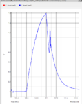
signal peaks i need to measure is between 10V to -5V. Signal looks like on the following photos.
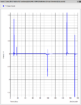
1.PNG
2.PNG

it needs ADC like around 30mhz i guess, and they can not measure wide analog input ranges. they measure 2V input range . I thought to use opamp voltage scale, would it be accurate enough, to zip voltage to 1V?
would you suggest any other method?

best regards
 

Hi,

for sure you can use a 30MHz sampling ADC. You can try to divide the voltage with a simple divider, or you may use an Opamp as buffer.
But maybe you don´t need that..

****
I often get jobs like this, then I find out the there are more simple solutions to come to the same result...therefore:

What is your goal?
* counting pulses?
* measure the amplitude of the pulse? (What amplitude: every single peak, an average of some pulses, the highest peak in a period of time...)
* you want to analyze the wavefrom? (like FFT...)
* calculate something else...

***
The waveform (timing) looks very random... where does it come from?

What impedance is the signal?

What precision and what resolution do you need? How to verify this?

Klaus
 
hi Klauss,
thank you for your answer,

it is voltage drop on an inductor.
i used a voltage scale with 3 resistors. pulled to voltage between 0-2V. and used 40mhz as you suggested.
the to measure voltage drop on the inductance during switching the semiconductor.
 

would you suggest any other method?

In general, reducing resolution, increases speed, and vice-versa. Without seeing in detail the requirements above, a possibility to be considered, and it is even adopted in some equipment to make reading beyond the maximum speed of the A/Ds, is by utilizing multiple converters in parallel, each of which performs sampling at intercalated intervals. I presume would be required to perform a post processing in order to calibrate the overal reading process, compensating differences on each convertor. In
 

Hi,

I see your post#3 .. but I can´t find an answer to my questions of post2...

In general I don´t understand what you mean..

Klaus
 

sorry,
What is your goal?
goal is the measuring voltage drop to calculate dic/dt.

The waveform (timing) looks very random... where does it come from?
it is switching frequency of the IGBT.
i dont know the impedance of the signal.
What precision and what resolution do you need?
i guessed any resolution after 8 would work fine.
 

Hi,

I´m still confused.

Please post a schematic.
Do you have any additional documents / links?

What is "dic/dt"?

Why don´t you have a fixed timing / constant switching frequency?

I don´t understand: "i guessed any resolution after 8 would work fine."

Klaus
 

Hi,
from the formula,
VL = L.diL/dt
with the voltage drop on the inductance, i want to calculate dil/dt, increase rate of the current.


frequency is constant, 1khz. it is parasitic inductance, only for test different time is used.
it is max -15volt till 15volt, 8bit should be enough.
 

Hi,

frequency is constant, 1khz.

How can you say that? Your scope picture with the peaks says something completely different.
I see 8us, 20us, 50us, 82us.... it has nothing to do with 1kHz.

Klaus
 

Hi KlausST,
these values are adjusted for double pulse test, for the simulation.
in real circuit it will work with 1khz.
 

Hi,

I´m even more confused:

What is simulation and what is real?
Is it now diL/dt or dic/dt?
What is dic at all?

I think I´m too dumb to follow...

Klaus
 

sorry ,

when the circuit comes, it wil work with 1 khz,
but on the simulation, i switched the igbt on different times, unabhangig from 1khz.

actually diL/dt and dic/dt is same, because
IC =collector current, dic/dt = increase rate of the collector current,
IL = current of the parasitic inductance.
IC = IL,
i hope i could explain better.

actually i am done with this, i made a voltage scale to have 0-2V and used 40MHZ adc.
best regards
 

Status
Not open for further replies.

Similar threads

Part and Inventory Search

Welcome to EDABoard.com

Sponsor

Back
Top