Continue to Site

Welcome to EDAboard.com

Welcome to our site! EDAboard.com is an international Electronics Discussion Forum focused on EDA software, circuits, schematics, books, theory, papers, asic, pld, 8051, DSP, Network, RF, Analog Design, PCB, Service Manuals... and a whole lot more! To participate you need to register. Registration is free. Click here to register now.

[SOLVED] 100A AC current measurement

Status
Not open for further replies.

Mithun_K_Das

Advanced Member level 3
Joined
Apr 24, 2010
Messages
899
Helped
24
Reputation
48
Reaction score
26
Trophy points
1,318
Location
Dhaka, Bangladesh, Bangladesh
Activity points
8,252
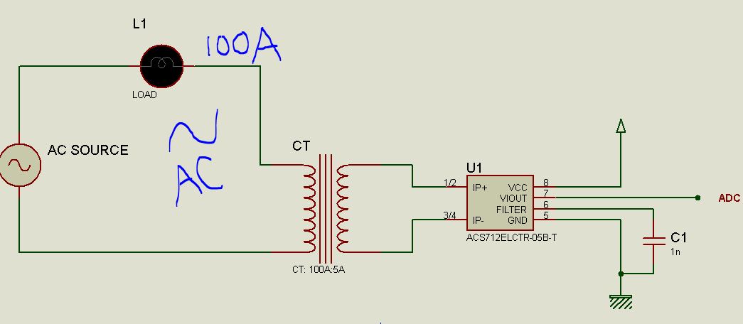
100A AC current measurement. Yes its a easy job to do with CT and Shunt resistor.

But if I use ACS sensor (hall effect current sensor) instead of Shunt resistor will it be a wise decision?

Will it be precious enough to measure up to 100A AC current?

I'm using 100A:5A CT and shunt resistor to ADC of microcontroller.
 

Hi,

Will it be precious enough to measure up to 100A AC current?
Read the datasheet. There should be the information about precision.

We don't know your application data nor the used sensor, therefore we can't answer your question.

Klaus
 

One advantage of a CT is that you can put a bridge rectifier before the burden resistor and then your adc only has to measure unipolar (all +ve ) half cycles with respect to ground.

A Hall sensor will need positive and negative power supplies and produce an ac output which can be inconvenient for an adc, unless it too can handle both -ve and +ve input.

Probably not too much difference in accuracy or linearity, but I suppose it depends on which has the most useful type of output.
 

Hall effect current sensor for 100A is available


**broken link removed**

CT-2.png
 

The output of the hall sensor ASC712-5A can be processed to measure the signal. But will it be wise to use instead using a burden resistor with CT secondary?
 

Hall sensor output will be in DC voltage but CT with burden resistor output will be AC
Ans also voltage level may be vary
 

I don't see an advantage in using a hall current sensor at the CT secondary. It adds noise, gain drift, a DC offset (to be compensated in software) and magnetic crosstalk to the measurement.
 

Actually ACS712 can measure both AC and DC current. Output is ac or dc as input. So no problem should be here with AC.

Actually I want to measure up to 1000A using different rated CTs. Such as 800A:5A, or 600A:5A etc.

So if I replace the burden resistor in the secondary of CT then it will be easy to measure the current. Also required space will be less than with resistor.

Here I attached an image of ASC712 datasheet.

Capture.JPG

But as I never used ACS712 with CT secondary before so I'm asking will it be wise to use hall sensor or I should use burden resistor of high watt?


Note: using a burden resistor will create power loss but hall sensor will not loss that much.
 

Normally your define what error you can allow then choose the best method.

Hall sensors are convenient and can be low cost but high cost for self-calibrated liner type

I prefer a 50~100mV shunt and have used this method up to 10kA
 

Hi,

before it was 100A , now it is 1000A.
You ask if it is precise enough, but you don´t say what precision you need.

If you use a low ohmic burden, then the dissipated power is also low.

Your posts lack a lot of informations and specifications. So it´s impossible to give good answers.

Klaus
 

What voltage isolation , peak current and accuracy is required.?

Core saturation and Remanence may occur if over driven.

A good design question lists your overall requirements™ These are "SPECS"
 

One advantage of a CT is that you can put a bridge rectifier before the burden resistor and then your adc only has to measure unipolar (all +ve ) half cycles with respect to ground.
.

You beat me to it, Tony. You have +16 hr timezone advantage...:-D

And with the properly sized burden resistor, they are indestructible.
I like to use current transformers for those reasons, when the measurement involves AC only. Of course, if there is a DC component, a hall cell must be used instead.
 
Hi,

before it was 100A , now it is 1000A.
You ask if it is precise enough, but you don´t say what precision you need.

If you use a low ohmic burden, then the dissipated power is also low.

Your posts lack a lot of informations and specifications. So it´s impossible to give good answers.

Klaus

Yes it was 100A before. Whatever, if I can measure 100A then I can measure 1000A too. All the CT s are rated x:5A where x = 100 to 1000A. So CT secondary is always 5A max.

I've designed one controller with keeping 3 resistors in parallel rated 5Ohm/50Watt each. So total resistance = 5/3 Ohms. I'm testing it today. Hope I post the result soon.
 

Hi,

A 100A:5A CT (or an 1000A:5A) is rated for RMS usually. So the output current is +/- 5A x sqrt(2) = +/-7.1A .. a total range of 14.2A.

If you have a 5/3 Ohms shunt then the output voltage is +/-11.8V a total of 23.6V but you talk about an ADC.
With 5A RMS this gives a power of 41.7W. Huge!

I assume your ADC has 0..5V input range: Then:
Why don´t you use an appropriate shunt to give +/-2.5V? = 0.35 Ohms (use 0.33 Ohms) then the dissipated power is only 8.25W and you don´t need extra circuitry to adjust to ADC input range?

You additionally could use a lower ADC_VRef. Maybe one to get 0...2.50V ADC_input_range.
Then a 0.15 Ohms resistor produces max. 3.75W of heat (use a 5W rated).

I see no benefit in using 3 pieces of 5 ohms...

Klaus
 
If all the "big fella" current transformers normally have a ratio to provide a standard 5 amps in the secondary, it should be possible to feed that five amps through a second much smaller current transformer mounted on the circuit board, to generate 5mA or 50 mA.

The power loss would then be negligible, and the small CT could be mounted up close to your ADC for minimal noise pickup. Its a win/win situation.

That is very good idea. Thanks.

I tested the circuit today. And lots of heat is generated. I think I should use another small CT to calculate the big line current.
 

Hi,

before you worried about precision... now you consider to use two CTs in series. This won´t improve precision...

Klaus
 

Status
Not open for further replies.

Similar threads

Part and Inventory Search

Welcome to EDABoard.com

Sponsor

Back
Top