Continue to Site

Welcome to EDAboard.com

Welcome to our site! EDAboard.com is an international Electronics Discussion Forum focused on EDA software, circuits, schematics, books, theory, papers, asic, pld, 8051, DSP, Network, RF, Analog Design, PCB, Service Manuals... and a whole lot more! To participate you need to register. Registration is free. Click here to register now.

Problem in Triggering Multiple Relay

Status
Not open for further replies.

CutieJocelyn

Newbie level 4
Joined
Aug 19, 2016
Messages
5
Helped
0
Reputation
0
Reaction score
0
Trophy points
1
Activity points
38
Hello,
In transmission circuit were using a 5V relay that has Contact DC Max Rating R Load of 3A@24VDC for the conversion of the pulse into a DC voltage. Were having a problem in triggering all the relays with a supply of 9V battery, we also tried to use a AC-DC supply using 7V input but it triggered only some of the relay. Is there any suggestion for the supply that can trigger all the relays? We're using a total of 24 relays. The model of relay that we used was UASH105D. Relay.JPG
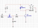
 

Start with a simple calculation applying ohms law. Total current to drive 24 relays with nominal voltage of 5V is 1.75 A.

So you need a transistor switch and a power supply that can handle the current.
 
Can I use TIP150 instead of BC547? It's collector current is 7A.
 

TIP150 is a Darlington transistor with up to 1.5V Vce,sat. Better use a NMOS FET.
 

Variables that also affect switching are rectified voltage and decay RC time constant between pulses and the impedance and voltage of your pulse generator. If it is 50 Ohms, thats a problem. then with only 10uF with a decay time of 4.7ms, with a 8,3ms off time... thats another problem. A 4V threshold MOSFET would just barely work with the 0.7V drop on a 5V pulse. And have a long decay time when turned off, unless a Gate R loaded the cap.
 
It might be worth considering using the present circuit but using it's relay contacts to switch all the other relays. That gives least overall power dissipation and ensures maximum voltage to all the relays but be sure the contacts are rated to switch at least 1.75A DC.

Brian.
 
The 9V battery itself may be where the current limit resides.
They're not very stout (except for lithium ones, maybe).
And most wall warts aren't much better, I haven't seen any
that exceed an amp rated and most have lousy I-V curves
and poor regulation under load.

You should be measuring stuff rather than asking for random
speculation.
 
The above schematic is just a single circuit. We will be using 24 relays so it means that the above circuit is also 24 connected in parallel.
 

The purpose of the capacitor in our circuit is just to stop the continuous triggering of the relay. Whats the purpose of replacing it by 47uf?
 

If you are duplicating the whole circuit 24 times, there will be no problem. But I guess you are just adding 23 more relays in parallel, right?

You need to figure out if the relay is on or off; if on, ignore additional triggers. If off, wait for the trigger pulse.

If not critical, think of introducing random delays between the relay turn-on:s. That will be just showing some kindness on the power supply.

I guess all the 24 relays are being turned on simultaneously with one common trigger?
 

No. We are not just adding 23 more relays. We are duplicating the above circuit 24 times, not just the relay.
 

The purpose of the capacitor in our circuit is just to stop the continuous triggering of the relay. Whats the purpose of replacing it by 47uf?

Can you provide some scope waveforms on base and collector?

This design is very "sub-optimal" and your power and signal source is poorly defined for source impedance.
Consider a transistor saturated only has a current gain to 10 to 20 at Vce(sat) thus Rb must be reduced 24 times then the Cap must be increased, which not be practical.

Higher value coil DCR ( "Sensitive version" ) would improve results

Thus a low RdsOn MOSFET is better << 10% of the load resistance ( pref 1% )

A transistor is a high speed switch but poor at current gain when saturated.
A Relay is a slow speed switch but better at conduction loss and has high effective current gain if you consider contact/coil current ratios.
A MOSFET has the highest current gain if you consider only slow speed switching and neglect gate charge current pulses.

WHen a transistor has high hFE (> 200) always look at Vce(sat) vs I and note the typical specs are 10:1 for Ic/Ib but with higher loss you can get away with 20:1 or better with some transistors from Diodes Inc. (50:1)
 

Status
Not open for further replies.

Similar threads

Part and Inventory Search

Welcome to EDABoard.com

Sponsor

Back
Top