Continue to Site

Welcome to EDAboard.com

Welcome to our site! EDAboard.com is an international Electronics Discussion Forum focused on EDA software, circuits, schematics, books, theory, papers, asic, pld, 8051, DSP, Network, RF, Analog Design, PCB, Service Manuals... and a whole lot more! To participate you need to register. Registration is free. Click here to register now.

Isolated Zero Crossing detector - Only positive crossing detection

Status
Not open for further replies.

pradhan.rachit

Full Member level 3
Joined
Oct 30, 2013
Messages
161
Helped
22
Reputation
44
Reaction score
22
Trophy points
18
Location
Mumbai
Activity points
1,183
Hello Experts,

I have am constructing a circuit which requires isolated zero crossing detection, but only the positive half of it.

The standard ZCDs using a full wave rectifier and an opto-isolator produce pulses at both the zero crossings (positive and negative half)

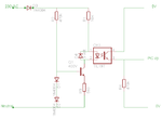
I found a circuit here https://www.chatzones.co.uk/discus/messages/12743/12815.html?1323198789 that half wave rectifies the signal and drives the opto-LED via a transistor.

I am not sure of its behaviour during the negative half of the input. Can someone please explain if and how it would fit my requirement?

Attached below is the image that I found.
12818.png


Thanks!
 

The first diode, D3 does half wave rectification. You will not see the negative half after that.

The base bias for the transistor is provided by the two diode drops. This voltage will be absent when the input voltage is absent (the negative cycle).\

Please ask more definite question- what exactly you are not understanding.
 

D3 does all the work, Q1 is just a constant current sink (~1mA) to prevent the IR diode being overdriven without sacrificing it's turn on voltage.

The LED current seems a little low for reliable operation and I can see no purpose for D4 whatsoever.

Brian.
 

Hi,

I totally agree with Brian.

Indeed it doesn't detect the "crossing" it rather detects the positive halfwave.

* D4 is useless
* I even find R1 useless
* I also find the current a bit low
* And a find R4 a bit too high ohmic. Expect slow, delayed edges.

Klaus
 

Thank you all for your replies.

What are your suggestions to convert this to a postive zero crossing detector?
Also, could you explain the formulae behind the component value calculation to make that network suitable to a 24VAC/50Hz system?
 

Thank you all for your replies.

What are your suggestions to convert this to a postive zero crossing detector?
Also, could you explain the formulae behind the component value calculation to make that network suitable to a 24VAC/50Hz system?

Reduce R1 and R2 by a factor of 10; if you want a higher current for the LED, make R2 about 100E. As suggested above, D4 may be safely skipped- it serves no purpose.

As pointed out in #4, this is strictly speaking not a zero crossing detector. This works everytime the voltage drops below a certain level. This can be increased by putting two diodes in series in place of D3.
 
Status
Not open for further replies.

Similar threads

Part and Inventory Search

Welcome to EDABoard.com

Sponsor

Back
Top