Continue to Site

Welcome to EDAboard.com

Welcome to our site! EDAboard.com is an international Electronics Discussion Forum focused on EDA software, circuits, schematics, books, theory, papers, asic, pld, 8051, DSP, Network, RF, Analog Design, PCB, Service Manuals... and a whole lot more! To participate you need to register. Registration is free. Click here to register now.

[PIC] Just bought an Arduino 1602 LCD Shield, help with correspondence to Proteus

Status
Not open for further replies.

Ragnar22

Member level 1
Joined
Aug 5, 2016
Messages
36
Helped
1
Reputation
2
Reaction score
1
Trophy points
8
Location
Lisbon
Activity points
267
HI guys, in the description of the device:
ftp://imall.iteadstudio.com/IM120417018_Arduino_1602_LCD_Shield/DS_IM120417018_Arduino1602LCDShield.pdf

Just seems confusing the way they describe it and the A0 to A5, apparently A1 to A5 should be D7 to D4 on my schematic right?
What about the other inputs, can I acess them? By the way I intend to use this with PIC16F887 probably to make a simple display of time and date with auxiliar RTC(ds1307). Thanks in advance.
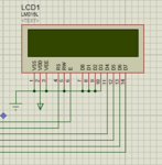


example.PNG


example2.PNG
 

There is no need to connect d0-d3 to ground, in fact it is better not to as the LCD has pull ups to VDD. You will need a potentiometer of 5k-10kconnected to the VEE line as otherwise you may only see black blocks.
The schematic seems correct as regards the LCD connection, although I would prefer to connect the RD0 to D4, RD1 to D5, RD2 to D6, RD3 to D7 and RD4 to D8. It does not matter but may make understanding the code a bit easier.

I didn't understand what your confusion was, D4 to D7 on your LCD board are your data lines which are the same as D4 TO D7 on your schematic.
 
Last edited:

Hi, thanks for the reply but my question is about the hardware connection with the shield itself because of the interface they created...
 

Looking at the PDF for the shield, it has the contrast control on it so you don't need to provide one, pin A0 is an analogue voltage output, the value of the voltage depending on what button pressed. D4-D7 is the data lines to the LCD wich are the same D4-D7 on the schematic. D8 which is the RS line which is the same as on the schematic. D9 is the E line which is the same as on the schematic. D10 is the back light control which should be connected to the 5v line, it maybe necessary to connect a series resistor here, check data sheet.
 

Status
Not open for further replies.

Similar threads

Part and Inventory Search

Welcome to EDABoard.com

Sponsor

Back
Top