Continue to Site

Welcome to EDAboard.com

Welcome to our site! EDAboard.com is an international Electronics Discussion Forum focused on EDA software, circuits, schematics, books, theory, papers, asic, pld, 8051, DSP, Network, RF, Analog Design, PCB, Service Manuals... and a whole lot more! To participate you need to register. Registration is free. Click here to register now.

Unwanted circuit coupling between PCA9685 and power line

Status
Not open for further replies.

Michielvsb

Newbie level 2
Joined
Aug 6, 2016
Messages
2
Helped
0
Reputation
0
Reaction score
0
Trophy points
1
Activity points
28
I'm working on a LED Strip controller project and I use the PCA9685 as PWM generator and now for test purposes I use a standard Arduino board as microcontroller. However on an oscilloscope I notice there are voltage spikes on the VDD pin of around 200mV each time the level of a PWM output changes.

The signal is measured at the Arduino 5V pin which is the power supply for the PCA9685.
DS1Z_QuickPrint1.jpg

The image is taken with a 470mF capacitor connected between Vdd and signal ground. I tried to use decoupling capacitors from 100nF up to 470mF between VDD and signal ground but there is no difference on the scope, there must be something that I don't know. Any suggestions on this?
 

It could be measurement error. Your scope probe needs to be using tip and barrel only across Vcc and Gnd .... ~ 1cm or less apart without gnd clip.

since ESR rises with C, the RC time constant is 10us for LOW ESR and about >>100us for standard. So when cable capacitance is switched current pulse causes a voltage spike at source due to ESR.

BIt more likely it is due to your ground clip ESL (.inductance)


If still noisy

the proper solution would be to decouple your Arduino with a choke to raise RF impedance with low DCR rated for load current.
 

There is surely no 470 mF capacitor in your circuit, might be 470 µF.

Power supply noise is just normal operation. Welcome to the real electronics world.

Bypass capacitors might show no effect because they are connected the wrong way, or you are measuring at the wrong circuit nodes.

It's necessary to look at the complete power supply and LED driver output wiring. Preferably show a photo of circuit design with bypass capacitors and probe connection.
 

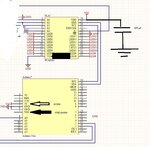
Ok here is a screenshot from my Altium schematic - I've put where I connected the probe and where I've put the capacitor. The actual ledstrips are not shown in the picture but they are 12V and powered from a lab power supply on a seperate ground line. The connection between the two grounds is made at the connection with the Arduino, so they have a seperate ground line. Whether the capacitor in this picture is connected or not makes no difference at all on the scope, and I cannot understand that.

schematic.jpg
 

Did you probe correctly as in#2 of
The reason is to reduce ground loop and ground inductance. If ripple is still too high, use very low ESR caps or shunt with 10uF tantalum

1738.scope_5F00_probes_5F00_gnd_5F00_wire.jpg
 
Last edited:

Your picture shows that you are measuring across 5V and VIN (which is a NC pin)?
 

Status
Not open for further replies.

Part and Inventory Search

Welcome to EDABoard.com

Sponsor

Back
Top