Continue to Site

Welcome to EDAboard.com

Welcome to our site! EDAboard.com is an international Electronics Discussion Forum focused on EDA software, circuits, schematics, books, theory, papers, asic, pld, 8051, DSP, Network, RF, Analog Design, PCB, Service Manuals... and a whole lot more! To participate you need to register. Registration is free. Click here to register now.

not starting bldc motor with using sensor

Status
Not open for further replies.

grayy

Newbie level 5
Joined
Jul 29, 2016
Messages
8
Helped
0
Reputation
0
Reaction score
0
Trophy points
1
Activity points
60
hello freinds...
I could start up the motor without using the sensors (of course motor doesn't work completely continuous and the speed was very low & there were quiet short stops beetween every rotation )
anyway leave it...
when i want to start up the motor with the sensors,it doesn't move at all...it's interesting that the micro can read the sensorso..apparently high power part of my circuit works truly..
how should i do?
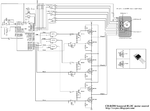
 

this is the related circuit..of course i have used IR2110 instead of 2N2222A transistors
there is IR2110 circuit in the other figure
please help
 

Attachments

  • circuit picture.png
    circuit picture.png
    215.3 KB · Views: 116
  • 2110BLDCSchematic_zps9d5a0550.jpg
    2110BLDCSchematic_zps9d5a0550.jpg
    46.2 KB · Views: 98

this is the related circuit..of course i have used IR2110 instead of 2N2222A transistors
there is IR2110 circuit in the other figure
You also changed PMOS to NMOS high side transistor. How can we know what's the real circuit?

One possible problem is that IR2110 driver doesn't necessary start with static level. There must be a dedicated start algorithm.
The other point is that we don't know the sensor to output logic implemented in your processor.
 

Hi,

The circuit is completely different now: different Mosfets, different driving mode, different count of driving signals....
So you show us two parts of schematic, and neither one is completely correct...

How do you PWM it now?
What PWM frequency?
What max duty cycle?
What does the scope show? Driver inputs, driver outputs, motor voltage...

Klaus
 

Without details of the sensors it is hard to be accurate, but I wonder if you should use an edge trigger from the sensor so the micro gets a " rotor passed point X" signal. At the moment you might still be getting an output from the previous sensor at the same time as the rotor generates the next sensor output.
Frank
 

setting up BLDC motor in PROTEUS

hello
?what is my problem in this PROTEUS circuit
please help
thanks
I attached the code but i can't attach the proteus file
 

Attachments

  • New Text Document.txt
    2.3 KB · Views: 93
Last edited by a moderator:

You don't tell an actual problem, how can we know what the problem is?

You can attach any file if you zip it before. Short code text should be appended to the post using code or syntax tags for reader's convenience.

The code suggests that you have been designing your decoder table and other details by trial-and-error method, but we don't know based on which information, e.g. motor datasheet, application note or whatsoever.
 

i attached it
please tell me my problem
 

Attachments

  • simulation.zip
    54.7 KB · Views: 83

Your code is a real mess; if you really want help, you should at least clean up all unused comments, which accounts more lines than compilable commands. At first sight it is possible to see things apparently meaningless, for example disabling/enabling interrupt in consecutive lines, disabling interrupts within isr vector(unnecessary on CCS compiler), etc... As FvM mentioned above, you could post the code not as an attachment, but righ here on the post - enclosed by proper tags.
 

The code can be functionally reduced to
Code:
int8 MoveTable[8] = {0, 33, 6, 36, 24, 9, 18, 0};

int main(void)
{
  while (1)
    output_d(MoveTable[(input_b() >> 4) & 7]);
}

You don't need interrupts to run it.

But what's the problem? How are you modeling the BLDC motor in Proteus?
 

so your code hasn't realy used sensor feedback..in your code, we put a array on the output connected to motor...
i had attached the proteus file at already post...
i uploaded it again
 

Attachments

  • simulation.zip
    54.7 KB · Views: 80

Your code is a real mess; if you really want help, you should at least clean up all unused comments, which accounts more lines than compilable commands. At first sight it is possible to see things apparently meaningless, for example disabling/enabling interrupt in consecutive lines, disabling interrupts within isr vector(unnecessary on CCS compiler), etc... As FvM mentioned above, you could post the code not as an attachment, but righ here on the post - enclosed by proper tags.


i haven't disabled the interrupt..i just have removed the flags by "clear interrupt" command..
of course i commented this comand but it didn't change anything
i attached the ordered code
 

Attachments

  • New Text Document (2).txt
    1.1 KB · Views: 61

so your code hasn't realy used sensor feedback..in your code, we put a array on the output connected to motor...

You may want to re-read this single line. Did you notice the input_b() function?
Code:
output_d(MoveTable[(input_b() >> 4) & 7]);

Unfortunately I don't use Proteus and can't check your simulation. A problem descriptions seems appropriate anyway.
 

Status
Not open for further replies.

Part and Inventory Search

Welcome to EDABoard.com

Sponsor

Back
Top