Continue to Site

Welcome to EDAboard.com

Welcome to our site! EDAboard.com is an international Electronics Discussion Forum focused on EDA software, circuits, schematics, books, theory, papers, asic, pld, 8051, DSP, Network, RF, Analog Design, PCB, Service Manuals... and a whole lot more! To participate you need to register. Registration is free. Click here to register now.

strong inversion region of mos

Status
Not open for further replies.

momoke

Newbie level 3
Joined
May 29, 2016
Messages
4
Helped
0
Reputation
0
Reaction score
0
Trophy points
1
Activity points
36
How to find the strong inversion region of a mosfet? In th book, I find, wenn gm/Id is smaller than 10S/A, is it in strong inversion region.

Is it always the same for different process?

I have also read some paper and some write, when Vgs-Vth0>100mv it is in strong inverison region.

Please help.
 

How to find the strong inversion region of a mosfet? In th book, I find, wenn gm/Id is smaller than 10S/A, is it in strong inversion region.

Is it always the same for different process?

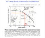
Yes. In this case the Inversion Coefficient IC ≥ 10 ; that' the definition for strong inversion.

See e.g. Binkley's book: Tradeoffs and Optimization in Analog CMOS Design , pp. 104 ff. Here's an image which shows this relationship quite well:
gm-over-Id_vs_Inversion_Coefficient_IC.png

I have also read some paper and some write, when Vgs-Vth0>100mv it is in strong inverison region.
About. This changes - dependent on the W/L ratio of the transistor used - between about >0.1 .. 0.4V

See also this forum's thread.
 
Hi, erikl. Thank you very much for your answer. I have read some of the book and some papers. I think I should plot the Ids-Vgs and Isq(so called sheet specific current)-Vgs with cadence. But I dont know how to plot Isq-Vgs.
Could you please help me some more?
 

I think I should plot the Ids-Vgs and Isq(so called sheet specific current)-Vgs with cadence.

I've never heard of a sheet specific current, sorry. Is it possible that you mix it up with a process specific current or Technology Current (called in Binkley's book)? This is defined as the drain current of a MOSFET with W/L=1 @ Vgs=Vth0 and Vds=Vsupply/2 . The threshold voltage Vth0 you can find in the MOSFET's model file, Vsupply is the recommended supply voltage for this MOSFET. (Vds=Vsupply/2 is my own interpretation: it's the mean operation voltage for a MOSFET in a circuit, and should reside in the saturation region for a MOSFET in such an operation condition.)

This Technology Current TC is the basis for the Inversion Coefficient IC of a MOSFET in its specific operation condition: IC = Ids/(TC*(W/L)).

Of course this Technology Current may (a little) be different for transistors with L=Lmin and L>Lmin , because for Lmin - in such operation condition - carrier velocity saturation and also vertical field mobility reduction (VFMR) will reduce Ids, and so the TC value. So I usually measure two different TC values for MOSFETs of a certain process: one for L=Lmin and one for L=5*Lmin , and of course separately for nMOS and pMOSFETs, and for each available MOSFET type in the PDK, which I'd use in my circuit.
 
hallo,erikl. Thanks a lot for your answer. You are right that I wanted to ask is technolog current. I have tried the things that you have told me. I set the w/l=1 and Vds=1/2Vsupply....Vgs=Vth to get TC, then I plot the gm/Ids VS Vgs and Ids/TC VS Vgs on cadence.
gmidvsIC.jpg
Then I merge the two diagram together to get gm/Ids VS TC. But the result is very weird. I think I did something wrong. But I cant find it. Could you please take a little of your time to have a look at the diagram. Thank you very much.gm_idvsIC.jpg
 

The 1st diagram is totally ok. The 2nd one - I guess the abszissa is Ids - is also correct; congratulations! Probably it would make sense to plot over log(Ids) instead of linear Ids .

Usually the required parameters are plotted versus gm/Id , or versus the overvoltage Vov = Vgs - Vth0 , see these example plots, pp. 8 ff: View attachment gm-Id_example_curves.pdf. I think a logarithmic representation (versus log(Vov)) would also be better in such case.

Personally, I'd find it better to use Ids or log(Ids) as abszissa, as curve representation of all the required parameters. Why? Because the Ids current is what I need to achieve the parameters which I want.
 
Status
Not open for further replies.

Part and Inventory Search

Welcome to EDABoard.com

Sponsor

Back
Top