Continue to Site

Welcome to EDAboard.com

Welcome to our site! EDAboard.com is an international Electronics Discussion Forum focused on EDA software, circuits, schematics, books, theory, papers, asic, pld, 8051, DSP, Network, RF, Analog Design, PCB, Service Manuals... and a whole lot more! To participate you need to register. Registration is free. Click here to register now.

TIP31 feeding about 25 leds (audiorhytm circuit)

Status
Not open for further replies.

Johanx2

Advanced Member level 4
Joined
May 13, 2012
Messages
113
Helped
1
Reputation
2
Reaction score
1
Trophy points
1,298
Activity points
2,636
Hi guys, I am in the way of put some leds to an active speaker that I am building. This speaker has 3 drivers, one is for bass, and two for voice and stereofonic sound. The amplifier board is one of those popular circuits you can find on ebay, which have two amplifiers class D, one bridged giving 100w to a subwoofer, and 50w+50w for the voice drivers. That board is bluetooth built in, and I have thought adding some leds to my enclosure, so these 25 leds will blink according to the music.

Somebody recommended me using the tip 31, which is a very simple circuit that is directly connected to power supply and audio source. But I just have some questions, althought I think this is what I am going to use.

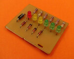
Here is the circuit I found. As you can see, its very simple, but one guy told me that it need a resistor in the base of tip31, otherwise it will be burned, Is that really true? considering that it is receiving a very weak signal that came from the pre amplifier, this thing is not connected directly to the speaker, so is that necessary that resistor in the base?

34q5hqp[1].jpg

The other 2 questions, is if I do this, I wont make the signal weak that pre amp out puts? or this thing will only take insignificant energy, that wont be noticeable? Other thing is that maybe I will need something in the base of the tip31, so I can control its gaing, what about a 5K potentiometer? but also can I put a low pass filter? so my leds will only blink with low frequencies, which is what I want. All the power consumption will be about 20mwx25 500w, I initially have thougt feeding all these leds by the last stage of the amplifier, considering that it gives 100w, 0.5w its like I am not stealing too much, and if I consider that the woofer will have a passive low crossover, I can feed the leds after this component. As you can see, I have many doubts with this, I hope ideas, there are ways to connect leds to the final stage of an amplifier using zener and resistors.
 
Last edited:

1. Putting a resistance in series in the base is a good habit to limit the base current but is not needed in your case. In fact, you can use a low pass RC filter instead.

2. You can also feed the base from the speaker terminals- that may be easier.
 

You show 4 LEDs but talk about having 25 LEDs. A red LED needs about 2V so four of them need about 8V. Twenty-five of them in series need 50V. Your circuit has a 12V supply that will blow them up without a series current-limiting resistor.
Of course the base needs a series resistor because the base-emitter is a diode that rectifies the high level signals from a preamp which causes severe distortion and the high levels from the output of a power amp will blow it up.
The maximum reverse voltage for the base-emitter of a TIP31 and for most transistors is only 5V so if driven from a power amp it needs a diode parallel to the base-emitter to conduct when the signal goes negative.

The circuit is too simple and will light the LEDs only during the loudest parts of the signal which might not happen often enough especially if the volume level is turned down. A VU meter with different levels for each LED is much better and it can have a peak detector so that you can see short duration peaks brightly.
 

1. Putting a resistance in series in the base is a good habit to limit the base current but is not needed in your case. In fact, you can use a low pass RC filter instead.

2. You can also feed the base from the speaker terminals- that may be easier.

Oh so theres no need for a resistor at the base, only in case to limit the gain of the light pulses, right? can I put a 1/4w - 5K potentiometer directly? Another thing is what you said, that it could be conveniente connecting the tip31 directly to the subwoofer terminals, in this case will be required a resistor at the base? considering that 100w will come in into the transistor.

What do you mean with a low pass RC filter? can I have an example? I can see it if I put a passive crossover to the subwoofer, so I can connect the transistor after it, so the transistor will only be excited by low frequency signals.


You show 4 LEDs but talk about having 25 LEDs. A red LED needs about 2V so four of them need about 8V. Twenty-five of them in series need 50V. Your circuit has a 12V supply that will blow them up without a series current-limiting resistor.
Of course the base needs a series resistor because the base-emitter is a diode that rectifies the high level signals from a preamp which causes severe distortion and the high levels from the output of a power amp will blow it up.
The maximum reverse voltage for the base-emitter of a TIP31 and for most transistors is only 5V so if driven from a power amp it needs a diode parallel to the base-emitter to conduct when the signal goes negative.

The circuit is too simple and will light the LEDs only during the loudest parts of the signal which might not happen often enough especially if the volume level is turned down. A VU meter with different levels for each LED is much better and it can have a peak detector so that you can see short duration peaks brightly.

I am going to use blue leds, which are 3.2V, I can make some groups, main voltage will be about 24V, that's not a problem. I need all the leds blinking at the same intensity and same time (no matter if volumen is 1/4% or 100%), so I don't need a vumeter like you mentioned, then I think that I will limit the voltage that transitors gets? so everything will be stable? I am now confused, and this is so simple.
 

What do you think about this idea? I have seen relays that can be trogerred with about 3V, I am talking about solid state relays, which are more convenient than mechanical ones. I will put one being trigerred by the speaker terminales, but I am going to put a 5v zener, so I wont compromise the relay getting more than it supports, although I have seen that they can support event 30V DC, anyway I think limitan they voltaje feedding means a more efficient load to its first stage, that way I am only taking a tiny part of the total power, the 30 leds or more are going to be feeded directly by the power supply, the relay will only create the on off pattern.
 

A little bit of knowledge can be a dangerous thing.

The original circuit will work *to a point* but it has serious limitiations:

1. for the transistor to start conducting it needs about 0.6v more positive on it's base pin than emitter pin. You won't get that from a pre-amp output.
2. If you connect it straight across the loudspeaker wires, you will get the voltage you need but it will CLAMP the voltage across the loudspeaker to about 0.8V and create horrible distortion. At high volume levels you also risk damaging the TIP31 and the amplifier.
3. LEDs, no matter what color are constant voltage devices, you have to limit the current through them and let them drop 3.2V by themselves. If you apply a higher voltage you risk burning them out.

To be honest, if you want a circuit with similar performance to that schematic, you would do better to wire the LEDs in pairs, one forward and one backward across each other (in parallel) then wire each pair through a 37 Ohm resistor across the loudspeaker wires.

What you are really asking for is a low pass filter, comparator and switched current source, it isn't complicated but needs more work than that simple circuit. It would meet all your needs exactly without risk to components and it would connect directly to the pre-amp output.

Brian.
 

Nice info betwixt, I have seen passive vumeters which are directly connected to the potency stage. What do you think if I add the low pass crossover between potency stage/speaker, and then I connect a 3-5 with resistor, so this will excite the solid state relay. We can adjust the gain by just changing the zener/resistor value, now the light will be more according to the light wave, which would be awesome, dont you think? and because it is a relay, I have infinite possibilities to switch what ever I want, all the leds connected directly into the main power supply, and not at the amplifier output. Is good this idea? I barely know electronics, I dont know anything about arduino or program software etc, I just know some componentes and know how to do some basic circuits.
 

Lots of ideas but none of them are really practical.

The VU meter doesn't work like LEDs even if they both give an impression of loudness. The VU meter is sensitive to very small voltages and only draws microwatts of power. The LEDs need more than 3V to operate them and require large amounts of power. The circuits to drive them are completely different I'm afraid.

I'm not sure what you mean by 'a 3-5' but you have to be careful with solid state relays, there are many types but the common ones for power control are completely unsuitable for driving low voltage LEDs. They rely on the polarity reversal of an AC supply to switch them off and if you use DC, as LEDs require, they never turn off at all - the LEDs will be on all the time.

You don't need to do any programming or use any kind of microcontroller, unless you want to of course. This is a straight forward analog task, it just takes a few more component than one transistor. I visualize something like this:

1. line out from amp - this is the low level signal from the pre-amp so it doesn't matter what the volume control is set to.
2. a low pass filter - just a few cheap components that stop it responding to anything except low (bass) notes.
3. a comparator - this converts the volume level you choose with a sensitivity control into a fixed higher voltage.
4. a MOSFET switch - this converts the comparator output voltage into an 'on/off' switch for the LED current.

The total cost for all this will only be about US $5 and it will satisfy all your requirements. You can also easily adapt steps 2, 3 and 4 for other frequency ranges in the future if you want to. For example flash red LEDS for mid range notes and green for high notes, you just use a different filter at step 2 and replicate steps 3 and 4.

Brian.
 

A little bit of knowledge can be a dangerous thing.


Brian.

Wise words have been spoken. As a matter of fact it should be one of the forum Mantras.

The OP seems to be receptive to comments though, and I also want to congratulate him for keeping an open mind and not stubbornly cling to a wrongheaded idea.
 

Re: TIP31 feeding about 25 leds (audio rhythm circuit)

What voltage is available? +\-50?
Line output is usually 1Vrms and fixed , is that avail?

This will be a convenient power source and determine array configuration of 3.2V LEDs in ser/par.

What dynamic response do you expect? There are many kinds which can be smooth, logarithmic, fast attack, slow decay, glow intensity with voice speakers with flicker to bass, etc.
fixed or variable sensitivity? change with volume control or fixed?

extra wires between amp and LEDs ? layout?
LED current?
I suggest strip LEDs SMD 12V nom but brightness controlled with gain then 8-16V for pulse music

Details depend on good answers.
 
Last edited:

What dynamic response do you expect? There are many kinds which can be smooth, logarithmic, fast attack, slow decay, glow intensity with voice speakers with flicker to bass, etc.
fixed or variable sensitivity? change with volume control or fixed?
I think the answer will be "flashing in time with the music" :grin:

Brian.
 

Sorry that I have done some grammar errors. The power supply is about 24V.
With 3-5 I meant a 3v to 5v zener with its a resistor (I have seeing passive led vumeter that are made of zeners, resistors, leds and nothing more, so I said, hey! all I need is to keep the first stage of that passive vumeter, which will be 3-5v zener, so that way I can connect the solid state relay there instead of a led, that way I would be able to switch as many leds I want using the main power supply and the relay acting as switch, there won't even be need for transistor, the solid relay will do everything.

Dont tell me you have not seein a passive vumeter like this? I seen a video an that performs really well, I am thinking in doing some modifications and and a solid state relay, this component wont be connected directed to the speaker, but just at a zener and resistor, then surely i will have a switch able to open close AC240V if I want. Is it not as easy as I thought?
 

Attachments

  • vu.jpg
    vu.jpg
    27.3 KB · Views: 117

We have all seen that kind of VU meter. The problem is the voltage and power needed to drive it. All those LEDs are small indicator tyes, they are not bright and the voltage needed to light each one is the LED voltage itself plus the Zener voltage plus the rectifier voltage. So the first LED in the chain (the first to light) which does not have a Zener diode at all, needs about 2.4V to start it lighting up. In terms of loudspeaker power, assuming 8 Ohm speakers, that means about 1.7V RMS or about 3.7W of power. If you use your blue LEDs, the first one will light at about 4.6W which is fairly loud. To get them all to light will take several tens of Watts.

Usually VU meters using Zeners are drive from high voltage rather than high power amplifiers. If you want a device like that, there are several rather old ICs that are purpose made to drive a chain of LEDs, either linear or logarithmic scaled called LM3914, LM3915 and LM3916. They will keep all the LEDs at the same brightness (the board shown wont) and be sensitive to much smaller voltages. These days, it is more common to emulate the LM391x devices in a microcontroller because it works out cheaper (~$1).

I would caution you again about solid state relays, the theory sounds good but they are far from optimized for this kind of application. You could be making a very expensive mistake instead of building some cheap and simple circuits.

Brian.

I think that you have not understand anything, I think, There wont be any led connected to the speaker terminal, I just going to put connect a zenner, a resistor and a solid state relay that can b excited by very low voltaje, that way I would be able to use the secondary of the relay to switch a lot of leds, all these leds will blink at the same rhythm, and that's ok because thats what I need, I need that effect, not several led increasing their patter of light. No now you got my idea of how to have 30 leds or more with arrhythmic effect taking the pulse from the speaker/relay and taking the energy from the main power source?
 

A zener diode, a resistor and the LED in a solid state relay all need voltage to conduct. Where will the voltage come from? Why use the zener diode that is not needed to simply turn the solid state relay on when the signal voltage is high enough? To make the signal voltage high enough then the signal must be amplified by a transistor or opamp amplifier because if it is driven from the speaker then the volume control can easily turn off all the LEDs. The solid state relay will turn on only at the loudest parts of the signal.

Do you want to drive 30 3.2V blue LEDs in series from rectified 240VAC which is 338VDC? They must be well insulated. Then the current-limiting resistor for 20mA will dissipate 4.8W. If one LED fails open then they all do not light.

The signal is AC but the solid state relay input is DC so it will rectify the signal which will cause its output and all the LEDs to flicker on and off at the signal frequency which causes the LEDs to be dimmed a little when they should be bright. Short duration pulses will be too short for our slow vision to see them brightly. My circuit avoids those problems by using a peak detector circuit.

It was a simple example, for example, if we put a 5v zener connected through the solid relay and the speaker terminals, then the relay will be maximum feed by no more than 5V, right? A zener of 5V or even more if convenient, the case is that I don't need the leds to bright more if volume is increased, this maybe is what you guys have not understood, my application does not need brighter leds if you increase the volumen, all leds will be al its maximum brightness as long as there is more than 5V at the speaker terminals, if voltage ups upto 20V, relay will be receiving 5V, is not it? and this will not affect al the leds I want to put in the secondary of the relay because this part is acting just as a simple switch, so you can switch whatever you want, 30 leds, a 120vAC bulb, I mean, these two contacts of the secondary coil of the relay are going to be in series with the circuit you want to switch. Then for example, all the leds are going to be connected directly into the power suply, with a open circuit, circuit that imagine who is going to close and open? the solid state relay!

To be honest, I don't know exactly how to connect this relay to the speaker terminals and if this is safe for amplifier and speaker, considering that speaker terminales receive more than 30V DC, there's more than enough energy to feed the 3v solid state relay, is that easy connect it into that? can I connected directly if voltage never reaches maximum voltage supported by primary solid coil of relay? or I simply do what that passive circuit vumeter did? I don't know how isolated should the relay be, but I think that my idea is awesome. I also thought in putting a microphone electrec, but that thing can be activated just by a car passing across your house, so it's not convenient. Please through me some schematics, I am close to build my project and need as much ideas as I can. Thanks so much!

Can I put an IC7805 which is feed by the speaker terminales instead of the zener? or will cause a kind of short? so maybe if so, the relay is more proper connected to the speaker terminals. I really have no idea.
 
Last edited:

A zener diode conducts when the input voltage is higher than its voltage rating. It cannot be connected in parallel with a speaker because it is almost a short circuit when the signal is negative and it is almost a short circuit when the signal is positive and more than its voltage rating.

You also do not understand a series circuit. A solid state relay has a 1.2V LED in its input. Its current is normally a few mA to turn it on but its maximum allowed current is stated on its datasheet and might be 30mA. If you add a 5.1V zener diode in series then it turns on when the input voltage is 1.2V + 5.1V= 6.3V. If the voltage is higher than 6.3V then it is destroyed by too much current unless a series resistor is added to limit the current. The resistor also needs voltage so the circuit needs about 10V or more to turn on. The signal is AC but the input of the solid state relay uses only DC and the negative voltage swing from the signal will destroy the solid state relay unless you rectify the input signal.

If this circuit is connected to the speaker terminals then the solid state relay will turn on at a signal level designed for it and will not turn on if you reduce the volume. If the volume is higher than designed then the solid state relay will be turned on for almost all of the input signal, not just the loudest parts.

Therefore it is best to have the solid state relay circuit driven from a signal before the volume control so that the volume control does not affect the sensitivity of the LEDs. A transistor or opamp amplifier will be needed to drive the solid state relay circuit.

A 7805 is a voltage regulator that needs a DC input. But a speaker signal is AC that will destroy a 7805. If you rectify the speaker signal so that it is DC pulses then the output of the 7805 will be 5V for most of the time and the LEDs will be turned on almost continuously unless you design the circuit with an attenuator to reduce the signal level to the 7805. But since you need an attenuator then you do not need the 7805. The attenuator will prevent the LEDs from turning on if the volume is reduced.

My sound indicator is like a VU meter with 10 steps of loudness to activate its 20 LEDs. The range of volume for the 10 steps is enough that low levels or high levels light at least one LED but usually 8 to 10 LEDs pulse with the beat of music of with a person's voice. The circuit's input is a microphone and it has a rechargeable battery for it to be portable.

You talked about the sold state relay switching 240VAC on and off. It will light an AC light bulb but destroy LEDs unless it is rectified into DC. A light bulb might not turn on fast enough to show short duration sounds.
 

A zener diode conducts when the input voltage is higher than its voltage rating. It cannot be connected in parallel with a speaker because it is almost a short circuit when the signal is negative and it is almost a short circuit when the signal is positive and more than its voltage rating.

You also do not understand a series circuit. A solid state relay has a 1.2V LED in its input. Its current is normally a few mA to turn it on but its maximum allowed current is stated on its datasheet and might be 30mA. If you add a 5.1V zener diode in series then it turns on when the input voltage is 1.2V + 5.1V= 6.3V. If the voltage is higher than 6.3V then it is destroyed by too much current unless a series resistor is added to limit the current. The resistor also needs voltage so the circuit needs about 10V or more to turn on. The signal is AC but the input of the solid state relay uses only DC and the negative voltage swing from the signal will destroy the solid state relay unless you rectify the input signal.
.


I see, then the most suitable circuit for my needs is the first schematic I showed in first post? I think that that goes after the pre amp, will I have a lose of sound quality when it is connected through one channel? or hows supposed to be connected that thing after the pre amp? If it make lose to a channel, that means that I need to make two of these circuitos and half the load? Look, I am making a sound box which has 30 leds, I need the leds to on/off all at same time and maximum brightness, no matter if volume is low or high, its easy, that's all need, I dont need patterns or led spectrum analyzers. So this circuit will be my trick?

broken link removed

- - - Updated - - -

A zener diode conducts when the input voltage is higher than its voltage rating. It cannot be connected in parallel with a speaker because it is almost a short circuit when the signal is negative and it is almost a short circuit when the signal is positive and more than its voltage rating.

You also do not understand a series circuit. A solid state relay has a 1.2V LED in its input. Its current is normally a few mA to turn it on but its maximum allowed current is stated on its datasheet and might be 30mA. If you add a 5.1V zener diode in series then it turns on when the input voltage is 1.2V + 5.1V= 6.3V. If the voltage is higher than 6.3V then it is destroyed by too much current unless a series resistor is added to limit the current. The resistor also needs voltage so the circuit needs about 10V or more to turn on. The signal is AC but the input of the solid state relay uses only DC and the negative voltage swing from the signal will destroy the solid state relay unless you rectify the input signal.
.


I see, then the most suitable circuit for my needs is the first schematic I showed in first post? I think that that goes after the pre amp, will I have a lose of sound quality when it is connected through one channel? or hows supposed to be connected that thing after the pre amp? If it make lose to a channel, that means that I need to make two of these circuitos and half the load? Look, I am making a sound box which has 30 leds, I need the leds to on/off all at same time and maximum brightness, no matter if volume is low or high, its easy, that's all need, I dont need patterns or led spectrum analyzers. So this circuit will be my trick?

broken link removed
 
Last edited by a moderator:

the most suitable circuit for my needs is the first schematic
I wonder why you still showing this circuit after all corrections that have been applied in the discussion? Still missing a current limiting resistor and coordination of supply voltage with number of LEDs.
 

If the threshold Vf of the string is about 1 or 2 LED Vf drops below the regulated supply voltage , V+, then there is no problem limiting the LED current using the transistor as an active series load and current limiter based on the input base current limiting resistor and current x current gain. However and understanding of hFE drops with saturation voltage also helps.

What is V+ and how many LEDs, transistor p/n and base R with input voltage are required. This can be from a preamp out or more, but each of these and the other characteristics must be defined to achieve best results.

Can you specify? y or n?

How do you expect it to respond exactly?
 

Status
Not open for further replies.

Part and Inventory Search

Welcome to EDABoard.com

Sponsor

Back
Top