Continue to Site

Welcome to EDAboard.com

Welcome to our site! EDAboard.com is an international Electronics Discussion Forum focused on EDA software, circuits, schematics, books, theory, papers, asic, pld, 8051, DSP, Network, RF, Analog Design, PCB, Service Manuals... and a whole lot more! To participate you need to register. Registration is free. Click here to register now.

[moved] 12 V DC to 115 V AC sine wave inverter

Status
Not open for further replies.

senan

Newbie level 5
Joined
Jun 29, 2016
Messages
9
Helped
0
Reputation
0
Reaction score
0
Trophy points
1
Activity points
74
unnamed.gif

Hi,

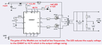
I am making a 12 V DC to 115 V AC sine wave inverter with the circuit attached. But I don't know how much power it can deliver. If it is a 10 W or 20 W or whatever the output power is. Can anyone help me with it and please suggest the components if I need to increase the output power.

Thank you :)
 

Re: 12 V DC to 115 V AC sine wave inverter

One factor is the amount of Amperes you can push through the primary loops. Parasitic resistance is a serious limitation here. You need to minimize resistance in every place you can: in the power supply, wiring and connectors, mosfets, and transformer.

In addition the step-up transformer is the heart of the converter. It needs to be built to work properly at your switching frequency.
 

In addition, properly sizing heatsink for the Mosfet device is a critical issue. As can be seen on its datasheet, the maximum allowed drain current decreases dramatically on increasing its case temperature.
 

The output is a squarewave, not a sinewave. Since your transformer needs 18V from each Mosfet but gets only about 12V then the output is only 77V or less at full power, not 115V. The peak voltage of a 115V sinewave is 163V which is more than twice as high as your circuit.

If the transformer is 10V-0-10V but produces 12V-0-12V at low current then the project will have an output of 115V at full power and 138V at low power but its peak voltage will still be much less than a sinewave.
 
  • Like
Reactions: senan

    senan

    Points: 2
    Helpful Answer Positive Rating
Re: 12 V DC to 115 V AC sine wave inverter

Thank you. But how will I know the power it can deliver, i.e if I want to connect a device which draws 20 W power from the supply. I would i calculate that.
 

If the load normally draws 20 watts at 115 volts, it will only draw about 7 watts at 68 volts output which is about all you are going to get using that transformer.
 

If the load normally draws 20 watts at 115 volts, it will only draw about 7 watts at 68 volts output which is about all you are going to get using that transformer.

Hi Tony,

What I am asking is, what power the above circuit can deliver(10W, 20 W or whatever).

Also the output pin 10, 11 is giving only voltage less than 5 V. But I am giving a 12 V supply.
 

Also the output pin 10, 11 is giving only voltage less than 5 V. But I am giving a 12 V supply.
Doesn't sound plausible at first sight. What's CD4047 Vdd?
 

The gate of a Mosfet is not a load at the low frequency of an inverter. The datasheet of the CD4047 shows that its outputs swing the entire supply voltage when it has no load. What is wrong with your circuit?
I calculate the supply voltage for the CD4047 to be +8.7V which is what its output voltage swing should be.
 

Attachments

  • squarewave inverter circuit.png
    squarewave inverter circuit.png
    38.7 KB · Views: 141

What I am asking is, what power the above circuit can deliver(10W, 20 W or whatever). .

The output power depends on the

1. power handling capacity of the output transformer
2. current through the primary windings
3. Supply voltage
4. inefficiencies

Questions:

Are you turning on the mosfets hard enough?
What is the Oscillator frequency being used?
You need to ensure that both the mosfets are never on at the same time.
 

Its pointless to build an inverter that can only put out about 70 volts, see post #4.

Even if it put out a million watts, what are you going to use a 70 volt inverter for ?
 

The inverter circuit has three problems:
1) The output is a squarewave instead of a sinewave like electricity has. Some electric products will not work.
2) The transformer is 18V-0-18V when it should be 10V-0-10V so that its output is 115V (instead of 77V or less using that wrong transformer).
3) The CD4047 needs to have an input and output of 10V (instead of 8.7V) to drive those Mosfets but the LED is loading down its voltage because the 330 ohm resistor value is too high.
 

Debug your circuit in a systematic and stepwise manner:

1. What is the voltage at the power supply pin of the CD4047?

2. What are the voltages at the output pins of the CD4047?

3. Are these voltages sufficient to turn on the mosfet?

4. How much current the transformer primary is taking?

5. What is the output voltage?

You will just need a scope and a DMM for these simple tests.
 

Doesn't sound plausible at first sight. What's CD4047 Vdd?
The Vdd range as per datasheet is 0.5 to 20V. So if I am supplying 12V Vdd my output should be at least more than 10V at the pins 10 and 11. Unfortunately its 4.8 V.
 

The gate of a Mosfet is not a load at the low frequency of an inverter. The datasheet of the CD4047 shows that its outputs swing the entire supply voltage when it has no load. What is wrong with your circuit?
I calculate the supply voltage for the CD4047 to be +8.7V which is what its output voltage swing should be.

Thank you for the calculations. I have removed the LED and the 880 Ohm resistor. Still the output pins 10 and 11 shows voltage around 4.8V. It should be at least something more than 10V.
 

Unfortunately you didn't yet manage to answer the simple question about the actual CD4047 supply voltage (pin16 voltage).

Presumedly there's something wrong with your real circuit, either wiring different from given schematic or defective components. Hard to determine from a distance.
 

Back to basics: How are you measuring the voltage on pins 10 and 11 ???
It isn't a steady voltage, it will (should!) be a near square wave which has an average voltage of only 50% of maximum. If you are measuring it on a DVM or moving coil meter you WILL get a wrong measurement and the chances are your reading will be about half of what it really is.

There is also a missing component in the design, it should have a capacitor across VDD and VSS of the IC for it to function properly. I suggest 10uF directly across pins 14 and 7.

Regarding output power, the theoretical maximum, ignoring the problems already mentioned is about 18W. In practice, if the problems are resolved, I would guess around 10W should be achievable.

Brian.
 
  • Like
Reactions: senan

    senan

    Points: 2
    Helpful Answer Positive Rating
Back to basics: How are you measuring the voltage on pins 10 and 11 ???
It isn't a steady voltage, it will (should!) be a near square wave which has an average voltage of only 50% of maximum. If you are measuring it on a DVM or moving coil meter you WILL get a wrong measurement and the chances are your reading will be about half of what it really is.

There is also a missing component in the design, it should have a capacitor across VDD and VSS of the IC for it to function properly. I suggest 10uF directly across pins 14 and 7.

Regarding output power, the theoretical maximum, ignoring the problems already mentioned is about 18W. In practice, if the problems are resolved, I would guess around 10W should be achievable.

Brian.

Brian,

I am using a DVM as you guessed. I don't have a CRO right now, lemme check the output with that.

As part of learning, may I know how you calculated the power delivered as 18W.

Thanks,
Senan
 

As part of learning, may I know how you calculated the power delivered as 18W.

That's an easy one: 18W from 12V means 1.5A has to flow. Any more than that will pop the fuse :lol:

Seriously, the circuit could be capable of producing much more power but to do so would require some extra circuitry. The fundamental problem is the MOSFETs have to work as near perfect switches, either not conducting at all or appearing to be a short circuit. You could think of them as being like mechanical switches turning on and off at 400 times a second. Unfortunately, they don't work like that and you will lose some power in their resistive losses. To minimize the loss, you have to ensure the voltage between the gate and source pins rises high enough and quickly enough and also drops to zero as quickly as possible. Each MOSFET works for half the time of each cycle, one is off while the other is on, then they both reverse, any time the gate is at an intermediate voltage, whether rising or falling, both conduct at once and they oppose each others magnetic fields inside the transformer. The usual fix is to add a 'dead time' period between the change over from one MOSFET to the other, it allows a short time for them to fully start or stop conducting before the other takes over. That requires some extra components though and in that simple circuit there is no way to add them easily.

You have:
MOSFET 1: H L H L H L H L
MOSFET 2: L H L H L H L H

You need:
MOSFET 1: H D L D H D L D H
MOSFET 2: L D H D L D H D L

where 'D' is the short delay (a few uS) while the MOSFET change over.

Brian.
 

The datasheet for the IRF540 Mosfet shows a maximum allowed current of 33A if it is cooled well enough. Other Mosfets conduct more.
It is the 1.5A fuse that limits the maximum output power of that circuit. If the fuse is 30A then the maximum output power will be 12V x 30A= 360W including heating.
 

Status
Not open for further replies.

Similar threads

Part and Inventory Search

Welcome to EDABoard.com

Sponsor

Back
Top