Continue to Site

Welcome to EDAboard.com

Welcome to our site! EDAboard.com is an international Electronics Discussion Forum focused on EDA software, circuits, schematics, books, theory, papers, asic, pld, 8051, DSP, Network, RF, Analog Design, PCB, Service Manuals... and a whole lot more! To participate you need to register. Registration is free. Click here to register now.

How to connect mic in parallel with loudspeaker

Status
Not open for further replies.

tomerbr

Junior Member level 2
Joined
May 6, 2008
Messages
23
Helped
0
Reputation
0
Reaction score
0
Trophy points
1,281
Activity points
1,478
Hi everyone,

I have a project in which I need to draw a signal from a car loudspeaker.

the configuration is to connect a cable in parallel to the speaker and connect it to a mic input in a sound card.

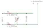
Now I know the impedance are very different and also the current that the mic will draw is much lower than what the speaker uses so I build a basic H-pad attenuator.
unfortunately I keep burning it up.

Might be that The power rating of the resistors are too small?
See configuration attached.

I would appreciate a solution, not necessarily related to pad attenuators.

Thanks.
 

Attachments

  • Attenuator.JPG
    Attenuator.JPG
    19.1 KB · Views: 111

This depends on the output stage of the car amplifier. If it is single ended, you do not need a resistor in the ground side at all, just connect it straight through. R1 is only needed if the loudspeaker is not present, it is there to fool the amplifier into thinking there is one present if in reality there isn't. The series resistor should be a much higher value, probably 10K or more depending on the sound card input impedance. If your amplifier has bridged output, meaning both loudspeaker wires are 'live', you shouldn't do this at all unless you add an isolating transformer.

I'm not sure what you aim to achieve doing this, the quality will not be good and there will be considerable background hiss. It is far better to connect to the audio before the amplifier and to use the sound card 'line in' input socket.

Brian.
 

Thanks Brian,

The goal of this project is to be able to control a radio with a computer automatically.
The computer will "listen" to the radio and will try to identify the station it is on. if it is on the right station, nothing will happen.
If it is on a non-predefined station the computer will switch it to the predefined one.

To achieve that I need a clean sound with low noise addition, otherwise the computer will not be able to identifies the station.
from what you explained I see my solution is not the the right one.

Can you (or anyone else) provide the right way to do.
I do no mind using IC circuits, or other components to achieve the goal.

Appreciate any help.

Thanks,
Tom.
 

1. Better to use a capacitor (1 uF) to provide DC isolation
2. Reduce the voltage by a factor of about 10-20 (to get line level signal) using resistor divider (output imp should be about 10K-47K- not very low)
3. Connect to the sound card input
 

Thanks,

1. Where to put the capacitor?
2. This is still forbidden for bridged output if I understand correctly right?
3. Don't have it, just microphone input.
 

The problem with a microphone input is it is designed to use a very small voltage from a microphone, typically 50mV or so. The line input would be good up to about 1V. Because you are using a more sensitive input, it will pick up amplifier noise and possibly interference, especially if the engine is running, and that might make it more difficult to ID the station.

The best place to tap in to the audio is before the car amplifier so you do not hear the extra noise it produces but that means surgery inside it which I'm guessing is out of the question.

The only safe and reliable way to use the speaker output is to isolate it with a transformer. That way will work regardless of the amplifier type and it will also avoid ground loops which tend to create havoc in automotive situations. Try it like this:

1. Get yourself a 600:600 Ohm audio isolating transformer.
2. If you are not using real loudspeakers, connect a 10 Ohm 10W resistor across the loudspeaker wires. If you are using speakers it isn't necessary.
3. Across the speaker wires connect one side (either will do, it's symetrical) of the audio transformer with a 220 Ohm resistor in series with it.
4. The other winding has one side connected directly to your computer ground.
5. Across the computer side winding, connect a 1K Ohm potentiometer, preferably with a logarithmic track (a volume control!)
6. Take your audio out from the wiper of the potentiometer through a 1uF, non-polarized capacitor.

You might try:
https://www.ebay.ie/itm/2pcs-JAMES-...713336?hash=item1c4612acf8:g:kYUAAOSwfcVUEvzK

for the transformer, the supplier is in your country.

Brian.
 
Just connect the speaker leads to a 10KΩ - 100KΩ potentiometer ends terminals, and the feed to the microphone input from its wiper and one end or ground. A tiny amount of level can be set by barely turning the potentiometer.
Test it with low radio volume to discern the wiper location, as you need just a few millivolts.
 

Tomerbr, I hope you understand that your circuit is not an attenuator. It is feeding maybe 8.5V RMS from the car radio speaker output directly to the mic input of the sound card that is expecting 10mV (0.01V). The sound card is probably damaged if the signal is higher than 10V p-p which is 3.5V RMS. If the radio's volume control is turned down then the computer will get nothing.

How does the computer know if the radio is on the correct frequency or is on a wrong frequency?
How does the computer know to increase the frequency or to decrease the frequency to find the correct station?
 

Most sound cards (including ones built in the mother board) have several inputs and usually have both microphone and line inputs. It is better to use line input because it is standardized and accepts higher voltage levels. Microphone inputs are really not standard and some are designed with ghost power. Some microphones produce outputs of the order of 10 mV whereas some others may produce outputs like 100 mV. If you have only micorphone input, you need to reduce the voltage level to around 50mV so that you will get an usable signal.

The microphone input will be single ended or if the input is stereo, you will need to feed the same signal to both.

If the radio is having a headphone output, you can use that directly. You may have to defeat the speaker turn-off feature.

If the radio speaker is floating (connected to a bridge), you will need to use two capacitors for DC isolation. Perhaps you can reduce them to 0.1uF.

Rest should be trivial.
 

I would be very cautious, even using two capacitors for isolation. If the ground is shared between the radio and the computer, which is a likely scenario, it would be loading one side of the speaker output with a capacitor to ground. It could cause instability and damage the amplifier. Using a transformer converts the output of any kind of amplifier to signal and computer ground, regardless of whether it uses a bridge or not.

Externet: many car radios use bridged ampifiers, the speaker wires carry anti-phase signals from two internal output stages to increase the available power without needing more supply voltage. Both speaker wires are therefore 'live' and grounding one of them through the computer sound card or even linking the channels together would risk damage.

Brian.
 
Thank you all for your answers.
I think I will go for the transformer solution.
One question though: why use 600:600 ohm transformer? why not use a 4-16:1000-10000 transformer as these are the impedance of the input/output sections?

Tomer
 

Basically, you already have too much voltage, if you use a conventional output transformer 'backwards' (loudspeaker to the 4-16 side) it will step the voltage up to several hundred volts when you really want to do the opposite. If you then try to reduce the voltage using resistor divider networks, you will mismatch the imedances again and possibly also create peaks and troughs in the the frequency response. A 600:600 transformer is a compromise but they are cheap, small and readily available. Best of all, they have a 1:1 voltage ratio and a mid-range impedance which is easy to work with.

The only other safe way to do it is with differential amplifiers but the circuitry will be far more complex and prone to noise pick-up.

Brian.
 

Ok, thanks.

I will draw a circuit and share soon.
 

Thanks again to you all.
Brain can you please verify the circuit.
By the way, using a 600:600 ohm (1:1 ratio) transformer will not change any voltage or current to my knowledge (I could be wrong) so I guess the attenuation is based on the resistors.
Can you elaborate on that a little? how this configuration will not harm the amp or mic and still produce the right sound?

Amplifier.JPG
 

You draw your schematics backwards. The signal source (the car radio) is supposed to be on the left side and the computer mic input is supposed to be on the right side.
The output from the car radio speaker output might be 7V RMS and the computer mic input might need only 0.01V RMS, a difference of 700 times.

If the car radio speaker output is 7V RMS (12.25W into 4 ohms) then the mic input gets about the same amount if the volume control is at maximum because your circuit does not have an attenuator. The 7V RMS (10V positive peak and -10V negative peak) into a mic input will probably damage the computer.

You must find out the power per channel the car radio produces continuously into a 4 ohm car speaker at fairly low distortion so we can calculate its voltage swing.
What is the computer listening for? Is the announcer saying the station's call letters and the computer is using speech recognition? If the station is the wrong one then what does the computer do to make the radio find the correct station?
 

Thanks,

About left/right is it not just semantic?
The connections will be the same no?
About my question on the attenuation, I didn't pay attention to the pot, it is of course a simple voltage divider hence the attenuation.

Can you please explain why the 220 ohm resistor and the capacitor (noise cancellation?)?.

Thanks,
Tomer
 

The schematic is electrically correct, it is just more conventional to draw the input on the left and output on the right although I can see an issue in countries where writing is generally R to L!

To explain:
The resistor is to drop the voltage, it is the first line of attenuation. The compromise is that if you make the value smaller you get less attenuation but if you make it too big, the frequency response becomes skewed by the transformer. It relies on being driven from a fairly low impedance to reduce the inductive effects and resonances that cause uneven passage of different frequencies. You could probably increase it up to about 1K before any serious degradaton takes place but how much you can tolerate depends on your computer appication.

The capacitor is there because the microphone input on your computer probably has a small voltage on it. Most computers sound cards (or on-board sound systems) place a voltage on the microphone input socket so they can power electret inserts, the most commonly used kind in headsets or hand held 'stick' microphones. Although the voltage is small and is limited in the current it can provide, if you fed it directly to the potentiometer and turned the volume down low, it might cause crackling or other noises due to the current flowing through the wiper to track contacts. The capacitor will make no noticable differnce to the sound but will block the DC current, making it safe.

Brian.
 
Thank you very much.

I will build it, test it and report the findings.
Probably will take me about a week until all the parts arrive

Thanks again,
Tome
 

Thanks guys, especially Brian, the suggested solution works.
 

Status
Not open for further replies.

Part and Inventory Search

Welcome to EDABoard.com

Sponsor

Back
Top