Continue to Site

Welcome to EDAboard.com

Welcome to our site! EDAboard.com is an international Electronics Discussion Forum focused on EDA software, circuits, schematics, books, theory, papers, asic, pld, 8051, DSP, Network, RF, Analog Design, PCB, Service Manuals... and a whole lot more! To participate you need to register. Registration is free. Click here to register now.

Need help with a circuit! Proper coordination of bulb, relay, regulator

Status
Not open for further replies.

DPluss

Junior Member level 2
Joined
Mar 2, 2016
Messages
24
Helped
0
Reputation
0
Reaction score
0
Trophy points
1
Activity points
230
Hello guys!

I'm a real beginner in electronics, I need a little help, I'll explain my circuit first, then I will get to the problem that I'm having issues to solve.

I am setting up a car signal light DRL like the what the US cars have, basicly dimming the 21W signal bulb by regulating the 12V input to 6V from my default parking light, so when I turn my parking lights on, the indicator bulbs come on aswell, and when I signal, it gets all the 21W it needs. But this is not the problem, I want to upgrade this by adding a relay, that switches between the 6V and the default 12V input, so when I turn on indicator it switches the relay so it breaks the 6V circuit and back to the stock 12V where the flashes are coming from and this way my 6v DLR isnt on while indicating! The problem is, that I cant power the realy with the indicators voltage because its momentary and it doesnt keep the relay closed... I tried experimenting with capacitors and adding another relay into the circuit, no luck... I'm thinking of somekind of timer thing that when I turn on the signal light, gets a signal powers the relay then after 0.6 seconds it shuts off the relay if it doesnt get a indicator signal again.

I know this probably sounds confusing, it is for me too, im really a beginner and any help would be really aprecciated! I'm looking for the easiest way to do this
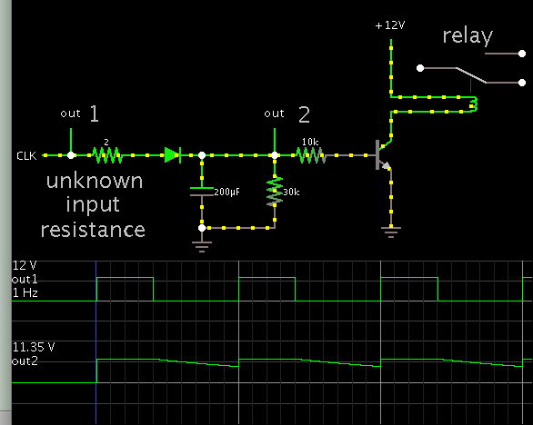
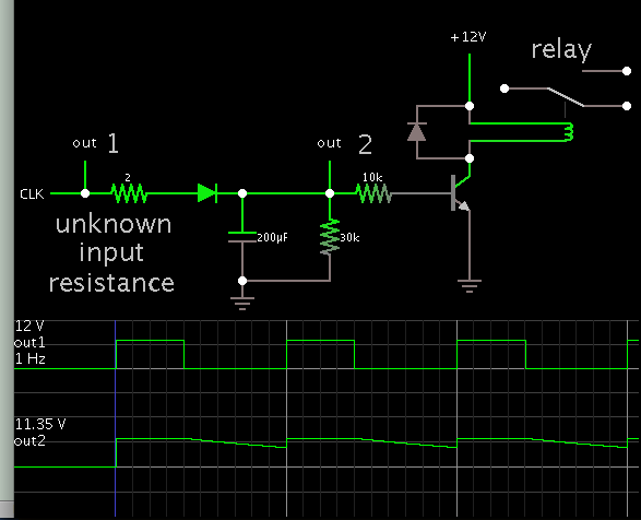
 :D

Here's the circuit:
cr1.jpg
 

It will be rather easier to figure out if you can make a chart - like a truth table - listing the various conditions.
 

It sounds as though you want to keep a relay activated for about 1 second each time after an indicator light flashes. Are you familiar with the 555 timer IC? It's a popular IC for generating timing intervals. It should be able to drive a relay. The time period is adjustable with a capacitor and a couple resistors.
 

It will be rather easier to figure out if you can make a chart - like a truth table - listing the various conditions.

I'm a cár mechanic, I have really basic knowledge of electronics, but ill try to come up with a proper chart

It sounds as though you want to keep a relay activated for about 1 second each time after an indicator light flashes. Are you familiar with the 555 timer IC? It's a popular IC for generating timing intervals. It should be able to drive a relay. The time period is adjustable with a capacitor and a couple resistors.

I was researching the 555 timer as I thought of it too, would the momentary 12v be enough for the 555 timer to keep the relay open for the adjusted time?(aprox. 0.6s the interval of one flash and one pause?
The problem is I have very little knowledge how the 555 works and what itneeds to operate, also I cant really find a source in my native language(hungarian) and some phrases are outside my english vocabulary :D

I could add another relay to the circuit that the 555 could operate which would power my original relay so I dont load the 555 circuit too much.
But all these ideas are theories to me
 

I believe most cars (perhaps all cars today) have the lights controlled by a microprocessor. It is not difficult to understand why- there are so many conditions- turning, braking, emergency flasher and the conditions can be really confusing. Often the same lamp is used for brake, turn and drive (I drive a car but I still do not know much about the electrical system and the control). I do not know how the 12V/6V supplies are derived and still less about the items that are supposed to be connected on at the first step of the ignition key.

Model T had a really user serviceable electrical system!!
 

The car im driving is using a light control module, but the circuit I am adding is after that control, I dont really know how to describe all the detaild but BradtheRad seems to understand what im trying tp achieve

Also I found this picture online that might help me, but its lacing some details I cannot calculate(capacitor voltage, resistor wattage)

7340648700_1467040862.gif


[from www . the12volt . com /images/turninglights.gif]

Instead of the output to the turning lights it would power my DLR relay
 
Last edited by a moderator:

Also I found this picture online that might help me, but its lacing some details I cannot calculate(capacitor voltage, resistor wattage)

You can safely use 25V capacitors and 1W fixed resistor (with ref to the .gif you posted).

(12V line from the battery can go upto 14.4V - say 15V and a 10V margin is a good margin for automotive electronics. 0.5W resistor will also do well in the same circuit and again 1W is a very good overrated resistor to be used in a vehicle)
 

Thank you very much for your advice, I will try it! Will post results after testing the circuit! Thanks again :)
 

Starting from the schematic in post #6...

This simulation fills in some component values. While pulses are incoming, the capacitor stays charged, sufficient to bias a transistor, which turns on a relay.


When the incoming pulses stop, the capacitor discharges completely after 2-3 seconds, and the transistor turns off.
 

Very nice, can you tell me what capacitor and resistors did you use? The relay only needs to be open for a second, also thank you very much for your dedication!
 

what capacitor and resistors did you use?

Look closely at the simulation to see values that work, in simulation anyway. You'll need to experiment, to find a capacitor value that drives the transistor for a second. Probably between 50 and 500 uF.

You might even try a darlington arrangement (two transistors). Resistor values need to be determined by experimentation. A potentiometer is convenient in this regard.

The resistor at left is unnecessary. It's there to make the simulation run smoothly.
 

When the incoming pulses stop, the capacitor discharges completely after 2-3 seconds, and the transistor turns off.
The transistor is driving an inductive load, should not be there a snubber circuit to avoid damaging the transistor?
 

You guys are the best! Thank you very much for your help, once my project is up and running, Ill post result and you guys will be credited for your help!
 

Once your project is up and running, you should also make a report. In your report, you should dissect the circuit into various elementary parts and explain in simple terms their roles and how they work and their selection procedure. If you have understood the basic principles, that will not be a problem at all. A good project must have a good report and a good report must be readable, informative and analytic.

(proper paperwork is always part of the job)
 

One more question, what kind of transisto should I use? What kind did you use in your simulation? and also I see that the relay coil has no ground, or I'm just seeing it wrong?
 

Any common NPN transistor (say 2N2222) will do because the relay may not take a large current. The relay coil is on the collector load and do not need ground connection. If the relay needs more than 500mA to turn on, you may need a bigger transistor. If the relay coil is marked for 5 or 6V, then you will need to add a resistor in series with the coil. The result will be as expected...
 

Im using a 12v relay OMRON G5SB-1 12VDC, according to its datasheet it needs 33mA, so i suppose the 2n2222 will work with this and without any resistors? (The 12v comes from the vehicle light so its stable, it wont go up to 14.3v as the generator chargers the battery)

- - - Updated - - -

also, I have some KSP 2222 ATA transistors(NPN 800mA/75V) lying around, would that work as fine as the 2N2222?
 

also, I have some KSP 2222 ATA transistors(NPN 800mA/75V) lying around, would that work as fine as the 2N2222?
Of course it will work, but generally higher transistor leads to slow it down, meaning it's turn on time and turn off time are higher than the 2N2222 which means power looses in commutation... Anyway, do not worry about that..

- - - Updated - - -

Actually I am seeing it's datasheet and seems like I am wrong. KSP2222A is faster than 2N2222A

- - - Updated - - -

Actually I am right :D. 2N2222A is higher rated than KSP2222A and hence slower. Show me datasheet where you saw KSP222A is rated at 800mA
 

Actually I misread, its 600mA :D It'll be still okay I guess...I'm gonna play around with different capacitors.

Still I dont understand the connection after the transistor on this picture of simulation a member showed me:

9921834300_1467071773.png

theres no ground on the relay coil? or am I just confused too much
 

Status
Not open for further replies.

Part and Inventory Search

Welcome to EDABoard.com

Sponsor

Back
Top