Continue to Site

Welcome to EDAboard.com

Welcome to our site! EDAboard.com is an international Electronics Discussion Forum focused on EDA software, circuits, schematics, books, theory, papers, asic, pld, 8051, DSP, Network, RF, Analog Design, PCB, Service Manuals... and a whole lot more! To participate you need to register. Registration is free. Click here to register now.

[SOLVED] Buffer output to microcontroller input

Status
Not open for further replies.

Prakash12345

Junior Member level 2
Joined
Jun 22, 2016
Messages
21
Helped
0
Reputation
0
Reaction score
0
Trophy points
1
Activity points
185
Hi,
I want to interface sensors to pic micro-controller(PIC18F87K22). For protection buffer(74HC541) is used in between them. Sink current of PORTH pins are 2mA. Other ports are dedicated to various operation. Buffer output current is +/- 35mA. Is this is a problem?
Resistor connected to serially will rectify sink current problem.
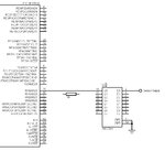
Input.jpg
 

Hi,

...almost the same discussion as some days before....

A short signal description:
Sensor output --> buffer input --> buffer output --> PIC input.

Please focus on "PIC INPUT"
An input does not sink current (in the range of 2mA). 2mA SINK = OUTPUT specification: from PIC_PIN to PIC_GND.

An input is very high ohmic. --> Impossible to draw current in the range of milliAmperes.

Buffer output current is +/- 35mA. Is this is a problem?
This is the MAXIMUM buffer output current. There the true current will be defined by the load = PIC_input. --> maybe in the range of microamperes.

Resistor connected to serially will rectify sink current problem.
"rectify" is not the correct term. What you mean is "limit"
--> A resistor limits the current.

****
With your added buffer you rather increase the fail rate than to decrease it.
* In case your PIC port is defined as "output" both, your PIC and buffer may go defective.
* In case of overvoltage from the sensor lines the buffer may go defective.

****
"For protection"... what does that mean?
The Buffer input will be the same sensitive as a PIC input. Therefore you don´t protect against damage, you just shift the damage form PIC to the buffer.
The costs to change the buffer will be more than the part price.

Isn´t it better to use "true" protection circuit to really prevent something to be damaged?
--> no fail, no need to change a part. --> true cost saving. Better overall reliability. More satisfied customers..


Klaus
 
Hi,

I'm using Inductive Sensor-M12.

2mA SINK = OUTPUT specification: from PIC_PIN to PIC_GND.
Please explain above quote briefly.

In datasheet they mentioned "Maximum output current sunk by PORTA<5:0> and any PORTF, PORTG and PORTH I/O pins- 2mA"
In my understand sink current means allowable current by device pins. Is this correct or not?

I adding buffer because any problem occurs that would not affect micro-controller, so only I using buffer.
Yes, I'm shifting the damage form PIC to the buffer.

My requirement circuit is reading signal through buffer. Please suggest solution.
Sink current.jpg
 

Hi,

SINK current applies to an OUTPUT.

But your PIC pin should be an INPUT.

therefore the SINK specification is not important for your problem.

****
PIC output pin sink current:

inside the PIC there is a transistor switching the output pin to GND. (Maybe a BJT, emitter to GND, collector to output pin)
This signal path is specified with a max allowed SINK current of 2mA.

****

Solution:
My solution is to PROTECT the circuit in a way to avoid damage.
There are several issues that may cause damage (of unprotected devices)
* high voltage, low capacitance, medium impedance voltage spikes in both directions: called ESD, HBM = statically charged body, touching pin with finger. small spark
* high voltage, low capacitance, low impedance voltage spikes in both directions: called ESD, MM = statically charged conductive material touching pin, spark
* high voltage low ohmic high energy pulse = burst pulse. caused by flash
* wrong connection = reversed voltage applied. low voltage = system voltage, 3.3V, 5V, 12V...
* wrong voltage, but correct polarity applied. maybe 12V at a 3.3V input pin.
* and several others.

You need to decide against what issue you want to protect, and what values. For some there are standard protection values. And standard test circuits.
Especially ESD pulses. Read through them.
And read through professional discussions about protection circuits.

You need to know about the danger. Example: You may invest a lot of time and mony to protect your house against fire .... but all is useless when there is a flood.

Klaus
 

Hi,
Ha ha ha, that's correct with your last Example @KlausST.

I just want to protect I/O pins from high voltage and current from external peripherals.

According to you my given circuit is correct without serious resistor?
 

Hi,

According to you my given circuit is correct without serious resistor?

Hard to say, because there are informations missing.

It is correct in this way: A logic level signal is fed through the buffer and fed into the PIC. Nothing more, nothing less.

We don´t know about sensor signal (voltage, timing, interface...)
It doesn´t protect against anything.
No information about PIC port setup, no information about PIC supply voltage, no information about buffer supply voltage..

*****
I just want to protect I/O pins from high voltage and current from external peripherals.
That´s what every I/O protection wants to do...
But what is "high voltage"? is ist 20V DC, 230V AC or 5000V ESD pulse?
How much energy?
What is high current? 50mA, 5A, 1000A?

--> protect against 20V DC is easily possible
--> protect against 230V AC is really difficult, because it´s never ending energy and the relatively high voltage.
--> protect against 5000V ESD HBM pulse is good to handle, but 5000V from a flash introduced by mains wires is difficult.

Similar this is with currents....

Klaus
 

Start with information about inductive sensor. There are NPN and PNP output types available. What's the sensor supply voltage?

24 VDC supply is industry standard. You should expect 24 V at the sensor output, at least in case of failure and higher transient voltage. Voltage divider and protection diodes required for µC input.
 
Hi,

NPN type
DC 3-wire (10-30V DC)

Mounting Distance -Shielded (2mm)
Sensing Distance -Shielded (0-1.6mm)
Power Supply -DC 10-30V
Frequency -DC: Shielded ≤ 600Hz
Current Output -DC: ≤ 200mA
Ambient Temperature--20°C to +70°C
Protection -DC: Over-Current & Polarity or no (Please Indicate when Ordering) / AC: no
IP Rating -IP67

My supply voltage is 12V.

For full details link given,
https://www.farnell.com/datasheets/1811994.pdf
 

Hi,

with this sensor you need a pullup resistor.

I´d choose something about 1k.

SensorInput.png


Klaus
 
Hi,

Fine, why we use 10k serially, is only for limiting current?
Then what about buffer output to micro-controller input?
 

If the buffer and the PIC use the same power supply voltage then the PIC input current is almost nothing, the high current available from the buffer output simply will not be used and will cause no damage.

It is the same as in a car. The battery can supply 600A (!) to the starter motor in winter but the clock using the same battery draws only 1mA or less.
 

Thank you all for your valuable suggestion. And at last my doubt is cleared.
 

Status
Not open for further replies.

Part and Inventory Search

Welcome to EDABoard.com

Sponsor

Back
Top