Continue to Site

Welcome to EDAboard.com

Welcome to our site! EDAboard.com is an international Electronics Discussion Forum focused on EDA software, circuits, schematics, books, theory, papers, asic, pld, 8051, DSP, Network, RF, Analog Design, PCB, Service Manuals... and a whole lot more! To participate you need to register. Registration is free. Click here to register now.

Solar System with Buck Converter Doubt

Status
Not open for further replies.

Bdrt

Junior Member level 3
Joined
Jun 20, 2016
Messages
28
Helped
0
Reputation
0
Reaction score
0
Trophy points
1
Activity points
265
Hello,

I'm studing a System for an array of solar panels (240W each, 16 in series).
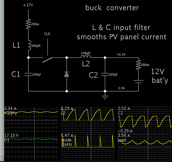
I'm considering using a buck converter to charge a high voltage battery pack (from 300V to 380V when full) from the pannels.

the circuit i'm considering is attached.

During the simulation of the circuit, when i use an ideal voltage source as Vi for the buck converter, I obtained a pulsed current (as the attached image )
When i placed a solar panel as Power source for the buck converter, the Input current was completly diferent. It was constant ( attached the image ).

Can anyone help me understand the wave forms and which one corresponds to the correct wave forms in a system like this ?

Thank you.

Simulation with pannel.jpgCapturar.PNGSimulation with ideal DC source.PNG
 

A PV panel can produce high V, low A...
Or it can produce vice versa.
Maximum watts comes at some midway values of V & A.

It helps to add an input filter at the front of your converter, so that you draw current smoothly and continually from the PV panel.

Looking at your schematic, it seems as though you have a smoothing capacitor at the input. Perhaps this performs some degree of smoothing? An inductor can provide further smoothing.
 

Hi

Are you able to show output wave forms with respect to different sources, hope you are doing simulation in PSIM it doesn't require any filtering for PV. Please post swtiching and out put when you connect PV.

thanks
 

Thank you for your answer.

Considering the functioning of a buck converter ( draws current from the panels while the switch is closed, dont draw current from the panel when it is open ) the power from the pannels is pulsed. In that situation can be complicated to find the power output from the panels to find if it is already on the maximum power point or not.
Because of that i did simulated the circuit with both a power source and a panel. The panel provided a constante output current even when it is not supling the load.

In a real aplication it would work like that ? the current would be constant or it would be pulsed ?

The purpose of this aplication is to charge the batteries with the maximum power suplied by the panel.
If the power from the panel is pulsed it can be hard to find if i am operating in the maximum power or not.

Am i right thinking this way?

you want the output forms from the converter? the converter has a PID control in order to keep a stable current at the charge (in order to do the CC/CV charching). I'm doing the simulation in PSIM. The output waves where the current is pulsed the that circuit with a DC source of 480V. The one where the current is constant is with a solar panel model from PSIM, where i introduce the values from the array of pannels ( Vmpp= 480 V, Impp = 16,1A , Voc = 600V , Isc = 17,12A ).

The idea is to implement the mppt with the buck converter in order to charge a battery pack with the maximum power from the panel.

Currently im still reseaching the best way to implement that. The buck converter is the easier to implement and to control as well as the one with least components.

Thank you.

- - - Updated - - -

Hi

Are you able to show output wave forms with respect to different sources, hope you are doing simulation in PSIM it doesn't require any filtering for PV. Please post swtiching and out put when you connect PV.

thanks

Thank you for your reply Darla.

You want the output waveforms from the buck with the diferent sources? im using a C block to implement a constant current control on the load.
Im using Psim. Those wave forms are from the same circuit but one with a DC power supply and other with a Solar panel model with the sollar array values ( Vmpp 480V , Impp = 16.1A , Voc = 600V , Isc = 17.12A)

My doubt is in a real system, with the buck converter, if the system will behave as with the simulation with the power source or the simulation with the panel.

Thank you.

- - - Updated - - -

Try to find any information about MPPT.

Hello Easyrider83,
thank you for the reply.

The ideia is to use the converter as mppt in order to allways charge the battery pack with the highest current possible.
I can find information about MPPTs but nothing tha clarifies my doubts.

Thank you.
 

This illustrates the LC filter which smooths the current waveform from a PV panel.


Notice the PV panel supplies constant 2.34 A. However see the waveforms going through the buck converter, peaking over 5A.

Perhaps your simulator's PV panel contains a similar LC filter? A simulator model of a PV panel is likely to be unusual. It certainly does not behave like an ideal voltage source. Occasional a poster asks how we might model a PV panel, but an easy method is not evident.

I'll try out the LC filter input. Thank you.

I've think the bevaviour of the panel may be related to the fact that it behaves like a current source and not a voltage source.
the electrical model of a solar panel is a current source with a diode in parallel and a series resistance.
Do you think that the wave form behaviour can be due to that?

The simulator has already a configurable solar pannel model, so i am using that instead of the electrical model.

Thank you
 

it probably has to do with the simulator which has as you state an "ideal" voltage source which implies that for any current drawn there will be no voltage drop. This would not be the case for a PV panel as when current is drawn the voltage drops and the feedback circuit will take this into account and not pulse. Well that is what happens in my circuits in real life and simulation. "Ideal" sources have no internal resistance.
 

The voltage pulses are changing after the 4th decimal point but the power and current fluctuates between the zero and max. Very strange.

Something similar to motorboating. You need to play with the simulation parameters, perhaps. Is the pulse frequency is related with the RC time constant? Acting like a relaxation oscillator?
 

You just need to fit a very large high voltage electrolytic capacitor across your PV panel array. That will hold a considerable charge, and smooth the pulsing current drawn by the buck regulator.

The PV panels then supply an almost constant charging current into the electrolytic.
The buck regulator is then able to source a much higher peak current at a (sometimes) very short duty cycle.
 

You have some boundary conditions - panel bus voltage max
and min, MPP current, battery charger input voltage and so
on. These would say whether a buck will do or whether some
corner might need boost capability. This all has to do with the
components at hand.

I'm sure you can find SPICE subcircuits or even a representation
for whatever schematic / simulation tool that was. But basically
your PV cell model is a big fat forward diode with a (photo)current
source pushing from cathode to anode. You would fit current to
solar conditions from panel electrical data if you were after
realism or useful what-if-ing.
 

Status
Not open for further replies.

Similar threads

Part and Inventory Search

Welcome to EDABoard.com

Sponsor

Back
Top