Continue to Site

Welcome to EDAboard.com

Welcome to our site! EDAboard.com is an international Electronics Discussion Forum focused on EDA software, circuits, schematics, books, theory, papers, asic, pld, 8051, DSP, Network, RF, Analog Design, PCB, Service Manuals... and a whole lot more! To participate you need to register. Registration is free. Click here to register now.

[General] how to build a board for any Microcontrollers?

Status
Not open for further replies.

rezaeee

Junior Member level 1
Joined
Oct 3, 2015
Messages
19
Helped
0
Reputation
0
Reaction score
0
Trophy points
1
Activity points
265
Hi
I want to learn how can I build a microcontroller based board?

for example. I have a project that I want read some sensor values, drive some motors, and transferring my data through Wi-Fi, Ethernet, etc. I do search in many microcontroller specifications and find a micro that it's good for my project. then I want to build a board because I can not soldering my sensors and motors and other modules directly to my microcontroller!

But the problem is here, I do not know how should I build my board? some body say you can search for other boards that built for that microcontroller you interested on and copy from it's schematic. and some other say there are the schematics you want to interface a micro in it's user manual and you must copy from it to build your own board.

But I am looking for a fundamental way to learn designing the circuits and building any boards I like with any microcontroller I choose!
 

My suggestions: distribute the work. Let us not get bogged down with one MCU doing all the work- sure it can be done but the overhead will be difficult to handle in a single program.

1. Sort out the information you will be needing from the sensors and get a driver that can talk to the MCU.
2. Same with the motors
3. Same with wifi and the ethernet.

Begin at the beginning: make a block diagram and decide the information you will need from each block.
Plan about the hardware drivers: do you need to have communication in both ways?

Then you finally need to plan what you are going to do with these information...
 

First make a block diagram. From that you can easily get the idea what kind beast you require (MCU) After that differentiate analog part from digital. If you sensors are analog then you may require signal conditioning circuit(Depend on your sensor type). Design the Signal conditioning circuit if required. Then come to Motor control part, Design the circuit for motor driver.
Last thing is wifi or ethernet. I would suggest using external module for that cause mcu comes with wifi support dont have that much enough horse power to handle other stuff. All your design should be around the MCU. i would suggest use MBED. Its easy and have builtin Ethernet, USB, etc etc. This beast is perfect for your requirements
.
 

Building a board for microcontroller might be difficult due to the interfacing devices. Google search pic, aduino, or ARM development board; will give clues on features of a board. Finally, I will suggest that the board should have a USB /serial interface, ICSP interface, header pins and power supply. Since all devices cannot be on the board, but can be in modules or breakout boards. Good luck.
 

Thank you all, your comments were great!
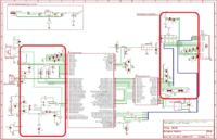
but my problem is a step before what you said. my study field was computer and I don't know many things about electronics. so when I want to interface a microcontroller like lpc 1768 with sensors, motors, ethernet or usb ports, then I find many pictures those are the schematics like the pictures i've added to this post. but the problem is that we can not connect them only with 2-3 or 4 direct wires and there are some circuits between them!

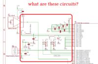
>> And my question is what are these circuits? how can I learn them? in with book(s)? Is there a short way to learn and know how they work and why they're there and how should I design them and use them to interfacing my microcontroller and building my board?


They are the hardware interfaces that are essential so that the two (sensor and the microprocessor) can communicate with each other. Each such interfaces have two ends; one connects to the microprocessor and the other end connects to the sensor. As there are so many different kind of sensors, you need to have many different kinds of interfaces.
 

Who designed them? how do they work?
if I want to interface my microcontroller to anythings, how should I design it's interfacing circuit?
should I go and read "electronics circuits" books and courses in university which those are about analog electronic design?
 

In post #5, in the first picture, I see one photodiode connected to an opamp but I cannot see where the output of the opamp is going.

Another sensor, just below, marked humidity/ temp sensor, is connected with one port of the microprocessor directly. The rest of the connections are for power, ground etc. etc. etc.

So are the most of the connections seen in the microprocessor.

If you want to interface YOUR microcontroller with something, you need to study the nature of input and output and the communication protocol. There is nothing more than that...
 

If you want to interface YOUR microcontroller with something, you need to study the nature of input and output and the communication protocol. There is nothing more than that...

Yes exactly I'm looking for this. is there a book or site or atleast keyword to search and find a good material to learn it?
 

You must check the datasheet for choosed microcontroller. In that datasheet you can find required minimal connections shematic.
 

L1 & C6 is a low pass filter for analog voltage supply for ADC module
L2 & C5 is a low pass filter for ADC reference voltage
for more advanced usage I recomend you to split ground poligons also
D2A and D2B is a voltage suppressors in one case to protect inputs from overvoltage spikes
R16 is a pull up resistor
C33 useless
C32 is a voltage filter capacitor for external sensor (bad idea to use same supply voltage inside the PCB and outside)
C1..C4 and C7, C8 is a filter capacitors for power supply of MCU. I suggest do draw all power related things on external sheet. Amount of them related from PCB layout and can be adjusted during tracing.
As you can see, nothing difficult)))
 

Take up a breadboard.
Take a small part of circuit.
Dont blindly copy circuit. Give time understand circuit.
do simulation in proteus or multisim
do it on breadboard and if that work repeat with other part of circuit.
If you dont understand the circuit dont go for board creation. WILL BE DANGEROUS(will kill your time :) )
You can get simulation from people who have already worked on modules download it and study will be easy for you.
Keep a long timesheet dont go in hurry
 

hi
i would suggest to take a few video lecture on "Basic Electronics" and also refer books on the same topic.
then you could go to some website like "http://www.kswichit.com/" and start from there..
 

Status
Not open for further replies.

Part and Inventory Search

Welcome to EDABoard.com

Sponsor

Back
Top