Continue to Site

Welcome to EDAboard.com

Welcome to our site! EDAboard.com is an international Electronics Discussion Forum focused on EDA software, circuits, schematics, books, theory, papers, asic, pld, 8051, DSP, Network, RF, Analog Design, PCB, Service Manuals... and a whole lot more! To participate you need to register. Registration is free. Click here to register now.

Complementary bidirectional switches

Status
Not open for further replies.

ctzof

Full Member level 3
Joined
Mar 1, 2012
Messages
157
Helped
12
Reputation
24
Reaction score
11
Trophy points
1,298
Location
Munich
Activity points
2,516
Hello,

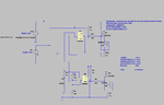
I want to design a simple circuit using the cheapest components as possible. I want to have two complementary bidirectional switches. When the control voltage is 5V one switch is open and the other close. When the voltage is 8V the first one is close and the second open. Is it possible to design this circuit dirty cheap using lets say just transistors?
 

You'll want to make a complete specification of the switches: E.g. Ron, Roff, voltage range, maximal current, available supply voltage.
 

You'll want to make a complete specification of the switches: E.g. Ron, Roff, voltage range, maximal current, available supply voltage.

Hi FvM,

As I wrote in my first post the control voltage is switching from 5V to 8V and this is my main and only supply. Maximal current I think doesn't exceed 30mA. The signal voltage range is from 0-5V. As for Ron and Roff I don't really know but I assume I want to keep them as low and as high as possible.
 

how much feed in from the control signal to the actual signal can you tolerate?
 

I want to have two complementary bidirectional switches.

A JFET can be bidirectional although its biasing method requires effort to get right.

Transistors/mosfets are not bidirectional but you might manage to add a DC component to your signal, so that those inexpensive basic components can carry it.

Also the 4066 IC (quad bilateral switch). It won't carry 30mA, so you'll need to locate one of its cousins.
 

....................
Transistors/mosfets are not bidirectional but you might manage to add a DC component to your signal, so that those inexpensive basic components can carry it.
.............
Mosfets are indeed bidirectional and conduct equally well in either direction.
That allows them to be used in applications such as synchronous diodes.
It's just that in one direction the substrate diode will conduct so a common MOSFET with the substrate connected to the source will not block in the reverse direction.

Maxim makes many low resistance analog switches, one of which should work for the OP's application.
You will need a buffer circuit or comparator to convert the 5v-8V control signal to the 0V-5V signal for the switch.
 

I wrote: 'Transistors/mosfets are not bidirectional...'

Mosfets are indeed bidirectional and conduct equally well in either direction.
That allows them to be used in applications such as synchronous diodes.
It's just that in one direction the substrate diode will conduct so a common MOSFET with the substrate connected to the source will not block in the reverse direction.

You are correct. I imagined (although we are not told) the OP has a signal, audio perhaps, which he wants to remain undistorted. Therefore I thought it should be a device which has 0V forward threshold, in both directions.
 

Planar (IC) MOSFETs are often symmetric and thus bidirectional.
Power MOSFETs (VDMOS or LDMOS) are very much not, with
body shorted ohmically to source.

Basically this sounds like a SPDT analog switch with a jacked
input threshold. Cheap enough piece-part, the input threshold
may just be a resistor divider or comparator?
 

I have designed a circuit based on a comparator and mosfets. Its true that mosfets (at least in simulation) don't work bidirectional so I had to add two mosfets connected back to back to create a bidirectional switch. At the moment the circuit works as I want but maybe is still expensive for my application.

For those who ask my signal is used to program the EEPROM of a chip so its pure digital with a range of 0-5V. Operating voltage is switching between 5V and 8V during normal mode and programming mode and basically I want to have two switches one is going to be closed in normal mode and open in programming mode and the other will behave the opposite way (open in normal mode and closed in function mode).

Can anyone suggest a cheaper way?
 

Attachments

  • circuit.png
    circuit.png
    37 KB · Views: 128
Last edited:

I've seen bidirectional I2C level translators from 3v3 to 5v, done exclusively with transistors and resistors.
Perhaps you can google that circuit and modify it to your requirements?
 

How is the VDD supply generated and what access do
you have, to it? For example if this is a close-in linear
or DC-DC regulator with exposed feedback network,
then shunting a piece of the feedback divider could
give you a bilevel output (slow, but accurate) for dirt
cheap (like one loose MOSFET and breaking the shunt
piece of the divider into two sections). If you only
wanted to shunt the piece that's connected to GND
then even an open-drain CMOS gate might do (one,
or parallel, outputs depending on the feedback network
impedances).

Bonus, you would not need the separate 8V supply,
just change the supply output to suit.

But if you had other "stuff" attached to this 5V source
then that could get stinky.
 

The circuit sketched in post #10 doesn't achieve the intended signal swing. The gate control voltage must be at least 4 V higher than the maximum signal voltage.

A switch with rail-to-rail voltage swing is usually implemented in CMOS topology. A low-ohmic analog switch IC would be a suitable solution.

That is true the final swing is from 0-3.3 V but this is not a problem cause the signal is still in margin to be recognised as high or low. On the other hand a switch is maybe a little bit cheaper.

Regarding the question about power supply I don't have any access on it. There is no LDR OR DC/DC in the pcb. In case of programming mode the voltage come and raised to 8V by the programmer.
 

That is true the final swing is from 0-3.3 V but this is not a problem cause the signal is still in margin to be recognised as high or low.

According to your previous specifications, I was assuming a true analog switch with 0 - 5V swing. Now it sounds like pure digital signal. Simpler transistor circuits can be probably used then.
 

According to your previous specifications, I was assuming a true analog switch with 0 - 5V swing. Now it sounds like pure digital signal. Simpler transistor circuits can be probably used then.

Can you suggest any circuit. As I said the application is cost driven. My design cost less than 0.3 Euros at the moment but I want if possible to go lower than that.
 

Status
Not open for further replies.

Similar threads

Part and Inventory Search

Welcome to EDABoard.com

Sponsor

Back
Top