Continue to Site

Welcome to EDAboard.com

Welcome to our site! EDAboard.com is an international Electronics Discussion Forum focused on EDA software, circuits, schematics, books, theory, papers, asic, pld, 8051, DSP, Network, RF, Analog Design, PCB, Service Manuals... and a whole lot more! To participate you need to register. Registration is free. Click here to register now.

Load cell weight variation in Platform with 4 load cell

Status
Not open for further replies.

anboli

Full Member level 2
Joined
Mar 9, 2012
Messages
144
Helped
4
Reputation
8
Reaction score
4
Trophy points
1,298
Activity points
2,512
Hi,

I having the Platform of 1700*800 with 4 mounting load cell. All the four load cells are connected together and given to ADS1230 IC. From the ADS1230 i getting the coount value through SPI Communiation. I retrieving all the datas, but my problem is, im not getting the constant value throughout the platform. When i kept the load in Top side of the platform it giving +50gms value and when i keeping at the down side of the platform it giving the -50gms Value.

For example: I keeping the 10Kg standard weight at acentre, it showing 10Kg. When i keeping at top side it gives 10.050Kg and at the down side it showing as 9.950Kg. How can i overcome this issue. And also i tried with the Load cell Junction PCB. This also giving the same result.

There is no issue while going with single load cell with small platform. i getting the perfect weight.
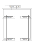
Load cell connecting diagram.png

ADS1230_Connection details.png
 

hi anboli,
Check the Vext at the upper and lower pairs of your load cells.
Your diagram suggests that you have 'shortened' the cable run to the upper load cells.
If so, this could result in an apparent reduction of sensitivity in the lower pair.

Are you confident that the problem is not caused by the platform design.?

E
 

Hi esp1,
I didnt shortend the cables. it running with full cable length what they given in the load cell.

I couldnt understand - "Are you confident that the problem is not caused by the platform design.?"

what will be the problem will occur with the platform design? if you have any idea, please suggest.
 

hi,
A problem I have had with platforms is ensuring that the platform is able to move freely on its base and is not 'binding'.

Did you design and manufacture the platform and base.?

E
 

The drift of 0,5% seems quite reasonable in a mechanical system (10,000±50)g. A zero-offset calibration could solve that, by placing the standard weight at each corner to get a multiplying constant for correcting deviations.

Anyway, are you sure the platform is horizontaly well leveled ?
 

Hi,

I'd say each load cell needs a unique gain calibration.
Offset calibration can be done in common.

Klaus
 

Platform is not freely movable, its is fixed with the surface and also its mounted horizontally.
I designed only the electronics part, remaining platforms are designed by mechanical team. I kept the level spirit on the platform, the level is not in the center, its slightly getting deviation with the center point.

- - - Updated - - -

The drift of 0,5% seems quite reasonable in a mechanical system (10,000±50)g. A zero-offset calibration could solve that, by placing the standard weight at each corner to get a multiplying constant for correcting deviations.

Anyway, are you sure the platform is horizontaly well leveled ?

Whether i need to place same (10Kg - 4nos)standard weight at each corner at the same time or else need to keep (10kg-1no)individual?
My platform is mounted horizontally. I kept the level spirit on the platform, the level is not in the center, its slightly getting deviation with the center point. whether this plays a role?
 

To check if it's a calibration problem, you would remove the platform and check if all four load cells have exactly same sensitivity in the parallel circuit, e.g. place the standard weight on each load cell one by one.

If it's no calibration problem, it must be a mechanical problem like unwanted sensitivity to transverse forces created by the platform design.
 

I think that calibration should take in account the platform itself. Although removing the shelf could in theory give a more accurate result, it could not be so valid depending on its weight copared to the load, particularly if we consider that load cells have some nonlinearity characteristic exhibiting sligtly different slope at different tensions. Perhaps just puting the standard weight at each corner at least could give an additional approximation for the calibration parameters, I guess.
 

Could i go with Load cell junction PCB?
 

Status
Not open for further replies.

Similar threads

Part and Inventory Search

Welcome to EDABoard.com

Sponsor

Back
Top