Continue to Site

Welcome to EDAboard.com

Welcome to our site! EDAboard.com is an international Electronics Discussion Forum focused on EDA software, circuits, schematics, books, theory, papers, asic, pld, 8051, DSP, Network, RF, Analog Design, PCB, Service Manuals... and a whole lot more! To participate you need to register. Registration is free. Click here to register now.

Power Supply Stability and Troubleshooting

Status
Not open for further replies.

E-design

Advanced Member level 5
Joined
Jun 1, 2002
Messages
2,014
Helped
507
Reputation
1,016
Reaction score
408
Trophy points
1,363
Activity points
14,193
This guy has a well-known YouTube channel where he covers a wide range of topics for the electronic hobbyist. He started a series on a DIY power supply for viewers to follow along and hopefully end up with a working design. Unfortunately, the series never made it past #14 due to unexpected stability issues that were discovered (7:00) in the design.
https://www.youtube.com/watch?v=gNJqL5Msa3s&index=13&list=PLDBuVMDVJaX2wCN84B5sjFMKDsMbsS7jq

As far as I can determine there seem to be a lot of people waiting for a solution to the problem, so they can complete the PSU. The last presentation was on Aug 14, 2015 where he touched upon the stability issues but never followed up with any solution.
https://www.youtube.com/watch?v=JBH5Eq9SYKs&index=14&list=PLDBuVMDVJaX2wCN84B5sjFMKDsMbsS7jq

I thought this would be a great topic for discussion by our members and help to come up with a possible solution to his problem. Beginners may learn something about the problem and solutions proposed by members.

This link is to the complete project and videos:

https://www.mjlorton.com/bench-power-supply-project/

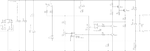
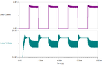
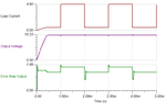
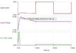
I did confirm doing my own transient simulation that the circuit as presented is plagued with oscillations.
 

Attachments

  • DIY_PSU.png
    DIY_PSU.png
    69.3 KB · Views: 95
  • stab_transient.png
    stab_transient.png
    20.5 KB · Views: 84

Ha funny, there's absolutely no feedback elements designed to reduce the gain with frequency, either on the current limit of voltage limit - this will cause oscillation where the knee point is reached, i.e. crossover between the two states - this is not a design created (or tested) by a power electronics engineer (i.e. with a BE).
I note it is vaguely stable at no load, but the Vo ave is way different, needs an hour or so of looking at and then suggesting values in the two loops to try...
 

From the information on the website, it appears that the design is from his college project many years ago, which seems to be working satisfactorily. Maybe there are some component variations to cause the latest rebuild to act up. To be stable over various load and voltage conditions, he will definitely need to apply compensation.
 

Maybe there are some component variations to cause the latest rebuild to act up.
E.g. compensation elements added by try and error method. Present circuit looks like "my first I/V controller design"...
 

a lot of inductance in the current sensing resistor will cause extra headaches for a start...
even a few b-e caps to limit RFI pickup may slow the loop enough to be stable - except at the transition point CV/CC

- - - Updated - - -

p.s. having too large an output Cap, requires very large base drive in order for the power stage to keep up with the control loop - so to design for unlimited C on the o/p (i.e. a large battery) there must be slew rate limiting components for stability...(or grunty base drive throughout the design - or a bit of both)
 

I made the following changes to the design that appears to simulate well over most output load variations:

1) Added two roll-off feedback capacitors of 100 pF each to both op-amps to limit overall frequency response.
2) Reduced R8 to 47 k.
3) Added a 390 pF capacitor over R15 for improved phase margin.
4) Added a 100 nF capacitor over ZD1 to prevent voltage overshoot on start-up.

This combination ended up with around 50-60° phase margin (varies with load and output conditions) according to simulation results obtained. Before compensation the phase margin varied between 11-19°.

Obviously, the only real test will be to have the hardware and evaluate with proper equipment. If anyone here happens to belong to the mjlorton forum maybe they can pass these modifications along for someone to try out on the actual project.
 

Attachments

  • diy_psu_stable.png
    diy_psu_stable.png
    17.2 KB · Views: 82
  • v_over.png
    v_over.png
    18.2 KB · Views: 79
Now we just need someone with this hardware to see if it produced the desired results. I have no plan to construct this PSU as I have more than enough units in my lab.
 

Status
Not open for further replies.

Similar threads

Part and Inventory Search

Welcome to EDABoard.com

Sponsor

Back
Top