anotherbrick
Full Member level 4
- Joined
- Jan 10, 2009
- Messages
- 217
- Helped
- 1
- Reputation
- 2
- Reaction score
- 1
- Trophy points
- 1,298
- Location
- Istanbul , Turkey
- Activity points
- 3,142
inverter theory - how can I bring the inverter to resonance ?
hello dear forum,
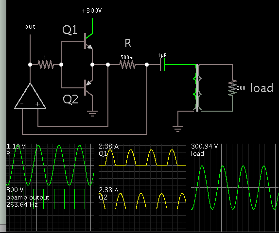
this below circuit is the schematic of an ultrasonic inverter

I want bring the circuit to resonance by playing with the value of inductance between output transformer and the piezo element
my question is ;
if I display the current and voltage at the 220 VAC input with the osciloscope - can I get an info if the circuit is at the resonance or capacitive or inductive behaviour ?
better said - if the circuit is capacitive or inductive for example would I see an out of phase scope display of input current and voltage ?
similarly , if the circuit is at the resonance is the line current and voltage in phase ?
thank you
hello dear forum,
this below circuit is the schematic of an ultrasonic inverter
I want bring the circuit to resonance by playing with the value of inductance between output transformer and the piezo element
my question is ;
if I display the current and voltage at the 220 VAC input with the osciloscope - can I get an info if the circuit is at the resonance or capacitive or inductive behaviour ?
better said - if the circuit is capacitive or inductive for example would I see an out of phase scope display of input current and voltage ?
similarly , if the circuit is at the resonance is the line current and voltage in phase ?
thank you