Continue to Site
Follow along with the video below to see how to install our site as a web app on your home screen.
Note: This feature may not be available in some browsers.
hello
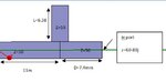
is S11 of single stub matching network must equal S22? and is it necessary for both to satisfied matching ?
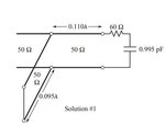
I can only tell you that it is a passive structure(circuit) and you can not have S-parameters greater than zero dB.
So there must definetly be something with your simulation setup or drawing in HFSS.
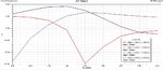
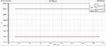
Hmmm....you have a constant impedance over the whole frequency range. That can not be possible for a frequency dependent network.