Continue to Site

Welcome to EDAboard.com

Welcome to our site! EDAboard.com is an international Electronics Discussion Forum focused on EDA software, circuits, schematics, books, theory, papers, asic, pld, 8051, DSP, Network, RF, Analog Design, PCB, Service Manuals... and a whole lot more! To participate you need to register. Registration is free. Click here to register now.

Power MOSFET driver for parallel power sources

Status
Not open for further replies.

aminpix

Advanced Member level 4
Joined
Sep 30, 2008
Messages
108
Helped
2
Reputation
4
Reaction score
2
Trophy points
1,298
Activity points
2,338
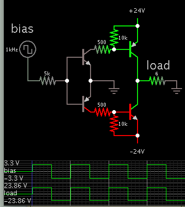
I am designing an inverter to convert +24 -24v to AC. my microcontroller is working with 3.3v.
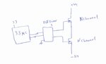
I don't know any proper FET Driver, that its low voltage side works with 0 to 3.3 and its high voltage side works with -24 to +24. like this picture, anybody knows?

broken link removed
 

Attachments

  • 201605111659_00000001.jpg
    201605111659_00000001.jpg
    46.1 KB · Views: 130
Last edited by a moderator:

Your +3.3V can drive an NPN, which in turn turns on a PNP. (They resemble a sziklai pair.) This method allows the PNP to turn off automatically, as its bias terminal is referenced to the positive supply rail.

(My simulation uses transistors instead of mosfets.)

5328907200_1463033458.png


A symmetrical arrangement will drive the negative section. However it needs a bias signal of negative polarity. Therefore you need -3.3V. You would need to add more circuitry, to be able to turn the negative section on and off.
 

Hi,

What about an optocoupler solution?

Klaus
 

Do you know any particular IC for that?
It is easier to use an IC rather than using BJT solution.
 

Hi,

You didn´t specify anything but voltage.
* load current
* switching frequency
...

Maybe a MAX14756/-7/-8 can also do the job.

*****
that its low voltage side works with 0 to 3.3 and its high voltage side works with -24 to +24.
It´s not low voltage and high voltage... its input side and output side.

Klaus
 

I plan to make an inverter, so the MOSFET current will be over 10A.
 

Your +3.3V can drive an NPN, which in turn turns on a PNP. (They resemble a sziklai pair.) This method allows the PNP to turn off automatically, as its bias terminal is referenced to the positive supply rail.

(My simulation uses transistors instead of mosfets.)

5328907200_1463033458.png


A symmetrical arrangement will drive the negative section. However it needs a bias signal of negative polarity. Therefore you need -3.3V. You would need to add more circuitry, to be able to turn the negative section on and off.

This circuit looks working but Vbias is between 3.3 and -3.3. but the micro-controller can only generate 0 to 3.3v.
 

This circuit looks working but Vbias is between 3.3 and -3.3. but the micro-controller can only generate 0 to 3.3v.

My simulation was merely to illustrate the concept. There are circuits which produce a negative polarity from a positive.

An optocoupler could be a solution (suggested in post #3). Things are simplified then, because you already have the -24V supply available.
 

Status
Not open for further replies.

Similar threads

Part and Inventory Search

Welcome to EDABoard.com

Sponsor

Back
Top