Continue to Site

Welcome to EDAboard.com

Welcome to our site! EDAboard.com is an international Electronics Discussion Forum focused on EDA software, circuits, schematics, books, theory, papers, asic, pld, 8051, DSP, Network, RF, Analog Design, PCB, Service Manuals... and a whole lot more! To participate you need to register. Registration is free. Click here to register now.

Buck Converter Simulation Not working

Status
Not open for further replies.

M.Rehan

Full Member level 2
Joined
Feb 10, 2016
Messages
129
Helped
2
Reputation
66
Reaction score
33
Trophy points
28
Activity points
972
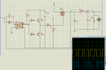
Can Someone simulate buck converter on proteus

Switching frequency 2kHz

Capture.PNG


View attachment Proteus.rar Proteus File
 

That circuit is not a proper converter design.
Q2 is upside down. The emitter needs to be up so it can act as an emitter follower, the same as the NPN does.

Q3 is configured as a source follower so it is never fully on, thus its dissipation will be high and the converter efficiency will be low.
It requires 50V at the gate to fully turn on (10V above the supply voltage), so you need a bootstrap driver for that.
 

First step: Correct obvious circuit errors:
- Flip Q2 emitter and collector
- Replace Z-diode D2 by a fast rectifier

Then check gate driver output voltage (voltage across R7) and correct component values if necessary. R3 and R4 are mostly useless, b.t.w.

Q3 is configured as a source follower so it is never fully on, thus its dissipation will be high and the converter efficiency will be low.
It requires 50V at the gate to fully turn on (10V above the supply voltage), so you need a bootstrap driver for that.
I thought the same, but the gate driver has a floating supply and can work. A bootstrap circuit could be a practical way to avoid the isolated power supply.
 

................
I thought the same, but the gate driver has a floating supply and can work. A bootstrap circuit could be a practical way to avoid the isolated power supply.
True. I missed that at first glance.
Isolated supplies are difficult in practice.
 

Simulation Still not working
Capture.PNGCapture1.PNG
 

Optocoupler pin 4 must rise to a high enough voltage, in order to turn on Q1 and turn off Q2.

- - - Updated - - -

Your output voltage is high. The cause could be a long duty cycle. This simulation has 10 percent duty cycle.

2953601200_1462549730.png


Notice a 10uF capacitor is sufficient to smooth the output to a reasonable extent.
 

Your pulse input to the opto is only 1 kHz in your attached example. At this low frequency, the required L and C value will be large. It is better to have the frequency above audible range (20 KHz and above)

Below I made a few changes and use a frequency of 20 KHz. Results are now more realistic. The transient start up choke current is shown on the green plot.
 

Attachments

  • 20k_buck.png
    20k_buck.png
    69.7 KB · Views: 94
  • 20k_buck_I.png
    20k_buck_I.png
    37.9 KB · Views: 85
  • Like
Reactions: M.Rehan

    M.Rehan

    Points: 2
    Helpful Answer Positive Rating
Is it possible to achieve 100% duty cycle in case of buck converter using bootstrap circuit (IR2110)?
 

Is it possible to achieve 100% duty cycle in case of buck converter using bootstrap circuit (IR2110)?
It's not possible. You need an auxiliary supply, e.g. a charge pump circuit to maintain a gate voltage above the positive supply. It's also important to reduce the quiescent current in on-state. Static current consumption as caused by R7 is unwanted.
 

Status
Not open for further replies.

Similar threads

Part and Inventory Search

Welcome to EDABoard.com

Sponsor

Back
Top