Continue to Site

Welcome to EDAboard.com

Welcome to our site! EDAboard.com is an international Electronics Discussion Forum focused on EDA software, circuits, schematics, books, theory, papers, asic, pld, 8051, DSP, Network, RF, Analog Design, PCB, Service Manuals... and a whole lot more! To participate you need to register. Registration is free. Click here to register now.

half bridge series resonant inverter

Status
Not open for further replies.

fancy_kyme

Newbie level 1
Joined
Apr 29, 2016
Messages
1
Helped
0
Reputation
0
Reaction score
0
Trophy points
1
Activity points
9
Hi, I am simulating a driver circuit(IR2110) to control and amplify the input voltage in Power Mosfets. My switching frequency is 37kHz and the output is 100W. The problem of my circuit is that during turn on of the Mosfets, there is a ringing at both of the output. How could i solve this problem?
Thanks a lot.
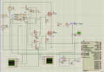
hbridge series resonant inverter.PNG37kHz.PNG
 

Your output stage is an LC 2nd order butterworth filter. This needs a load attached, or else it causes unexpected and unpredictable behavior.

Try a different switching frequency, to see if the ringing waveform changes.
 

What is I1? Are you really supplying the DC bus with a current source? That's weird.
 

Status
Not open for further replies.

Similar threads

Part and Inventory Search

Welcome to EDABoard.com

Sponsor

Back
Top